
Pneumatic tire

a technology of pneumatic tires and treads, which is applied in the direction of tyre tread bands/patterns, vehicle components, transportation and packaging, etc., can solve the problems of large amount of deformation of blocks. , to achieve the effect of suppressing the generation of above-described problems and large amount of deformation

Pending Publication Date: 2021-10-28
THE YOKOHAMA RUBBER CO LTD
View PDF0 Cites 1 Cited by
  • Summary
  • Abstract
  • Description
  • Claims
  • Application Information

AI Technical Summary

Benefits of technology

The present technology provides a pneumatic tire that has improved durability and performance on ice. The technology achieves this by controlling the shortest distance between the tire tread and the ground, which prevents tire chunk failure and minimizes cracks. Additionally, the technology ensures that the hardness of the tire tread rubber falls within a specific range, which optimizes rubber deformation and enhances rubber adhesion, leading to improved tire performance on ice and durability.

Problems solved by technology

When a compound having a lower hardness is used in the tread cap rubber, however, the amount of deformation of blocks is large at the time of contacting the road surface, and the rubber itself likely accumulates heat.
Furthermore, due to the fact that the large number of sipes are disposed, stress is concentrated on sipe bottoms, and when driving is continued under a low pressure and a high load state, a shoulder block having a relatively high ground contact pressure in the tread surface may break (referred to as tread chunk).
Thus, it is conceivable to increase the hardness of the tread cap rubber to suppress deformation of blocks, but the adhesion friction force will decrease to deteriorate the performance on ice.
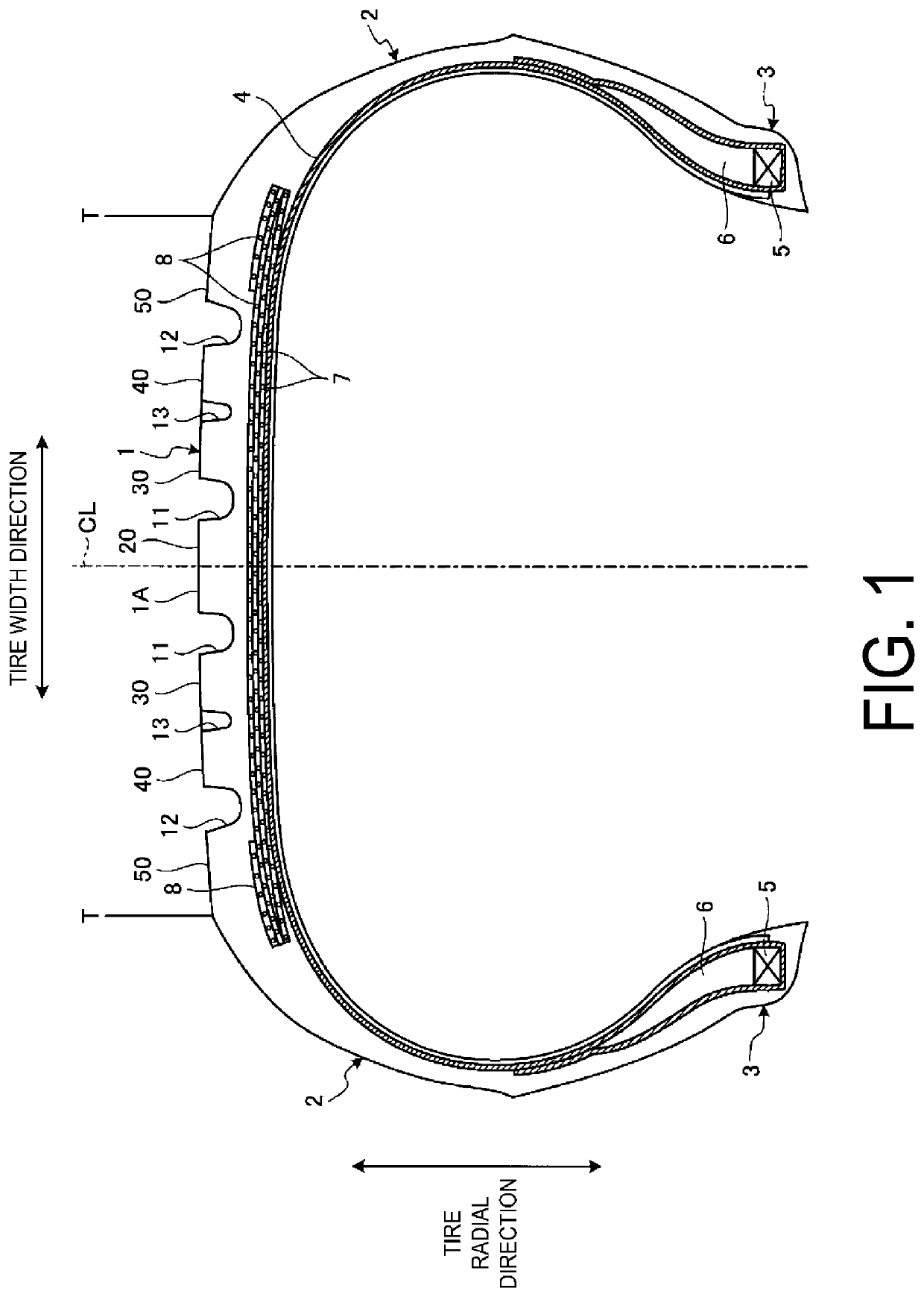
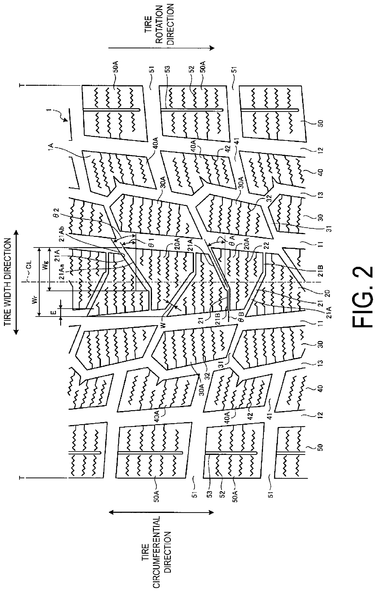
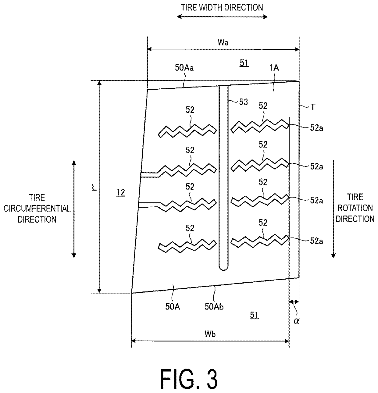
When the shortest distance exceeds 2.5 mm, the ground contact pressure of each of the plurality of shoulder blocks becomes excessive, and the failure of tread chunk is likely to be generated.
Conversely, when the shortest distance is less than 1.5 mm, the ground contact pressure is reduced, but the outer side edge in the tire width direction of each of the plurality of shoulder blocks and the end portion of each of the plurality of sipes are too close, and cracks are likely to be generated.
Furthermore, when JIS hardness Ha of the cap tread rubber forming the tread surface of each of the plurality of shoulder blocks is less than 45, the movement of each of the plurality of shoulder blocks when being in contact with the road surface during the rotation of the pneumatic tire is increased, the amount of the deformation is large, and the rubber itself accumulates the heat likely to generate the above-described problems.
Conversely, when the Ha exceeds 55, the adhesion friction force declines and the performance on ice tends to decline.

Method used


Image

  • Pneumatic tire
  • Pneumatic tire
  • Pneumatic tire

Examples


example

[0078]In the present Example, with respect to the pneumatic tire of above-described embodiment, performance tests for durability performance and performance on ice (braking performance on icy road surfaces) are performed on a plurality of types of test tires of different conditions (see FIGS. 5A-5B and 6).

[0079]In the performance tests, pneumatic tires of tire size 205 / 55R15.91H are used as test tires, and the test tires are mounted on regular rims of 16×6.5 J.

[0080]In the evaluation method for durability performance, the test tires are inflated to an air pressure of 180 kPa, and while a circumferential temperature is controlled at 38±3° C., the test tires are loaded with a load equivalent to 100% of the maximum load specified by JATMA and driven for 37 hours at a speed of 120 km / h, by using an indoor drum testing machine (drum diameter: 1707 mm). Thereafter, the test tires are inflated to an air pressure of 140 kPa and loaded with a load equivalent to 100% of the maximum load speci...


PUM


Abstract

A tire, comprising:a plurality of shoulder blocks side by side in a tire circumferential direction on the outermost side in a tire width direction, by a main groove extending in the tire circumferential direction in a tread surface of a tread portion and by a plurality of subsidiary grooves intersecting the main groove; and a plurality of sipes extending along the tire width direction in the tread surface of each of the plurality of shoulder blocks and provided side by side in the tire circumferential direction. Each of the plurality of sipes includes at least an end portion terminated on an outer side in the tire width direction, a cap tread rubber forming the tread surface has JIS hardness Ha of in a range of not less than 45 and not greater than 55, a snow traction index in a 0° direction is less than 180.

Description

TECHNICAL FIELD[0001]The present technology relates to a pneumatic tire.BACKGROUND ART[0002]In the related art, for example, the pneumatic tire described in Japan Unexamined Patent Publication No. 2018-039337 is designed to improve load durability performance while ensuring performance on snow and performance on ice. The pneumatic tire includes, in a tread surface in a land portion, a surface processing portion including a plurality of inclined narrow grooves inclined with respect to the tire circumferential direction; a plurality of sipes extending along the tire width direction and intersecting the plurality of inclined narrow grooves of the surface processing portion and arranged side by side in the tire circumferential direction, each of the plurality of sipes being separated midway while extending along the tire width direction; and[0003]a recess portion spaced away from an end portion of each of the separated plurality of sipes at a gap where each of the plurality of sipes is ...

Claims


Application Information

Patent Timeline
Patent Type & Authority Applications(United States)
IPC IPC(8): B60C11/00B60C11/03B60C11/12
CPCB60C11/005B60C11/0008B60C11/0306B60C11/1204B60C11/1236B60C2011/0351B60C11/1263B60C2011/0016B60C2011/1254B60C2011/1213B60C2011/0348B60C11/0302B60C11/13B60C11/11B60C2011/0346B60C11/032B60C11/1259B60C11/12
Inventor NUKUSHINA, RYOSUKE
Owner THE YOKOHAMA RUBBER CO LTD
Learn More