Joining structure
a jointing structure and joint technology, applied in the direction of welding apparatus, manufacturing tools, transportation and packaging, etc., can solve the problems of more disadvantageous rigidity of structural members in resisting spot welding than continuous welding, and achieve the effect of reducing weight, high rigidity of structural bodies, and good balan
- Summary
- Abstract
- Description
- Claims
- Application Information
AI Technical Summary
Benefits of technology
Problems solved by technology
Method used
Image


Examples
first embodiment
[0085]A first embodiment of the invention will first be described. As already described, the automobile vehicle body includes a side sill and a lower A pillar as structural members. In the following first embodiment, a form in which a joining structure of the invention is applied to a joining structure between the side sill and the lower A pillar will be described.
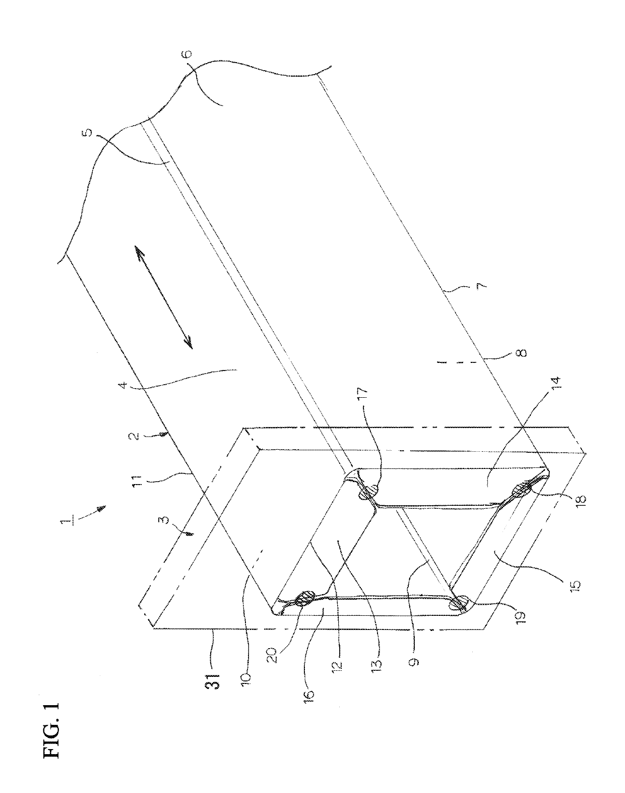
[0086]FIG. 1 is a perspective view schematically illustrating a joining structure 1 (the joining structure between a side sill 2 and a lower A pillar 3) related to the first embodiment of the invention. FIG. 2 is a view when the joining structure 1 illustrated in FIG. 1 is seen from the lower A pillar 3 side.
[0087]In addition, although the joining structure 1 between the side sill 2 and the lower A pillar 3 will be described in the first embodiment, the invention is not limited only to this form. Respective shapes of the side sill 2 and the lower A pillar 3 are simplified and illustrated in FIGS. 1 and 2. Additionally, in ...
second embodiment
[0146]Next, a second embodiment of the invention will first be described. As described with reference to FIG. 23, the automobile vehicle body includes a side sill inner panel, a side sill outer panel, a first reinforcement, and a second reinforcement as the structural members. In the second embodiment, a form in which the joining structure of the invention is applied to a joining structure between these structural members will be described. Additionally, at least one of the above first reinforcement and the second reinforcement may be a center pillar inner panel.
[0147]FIG. 15 is a perspective view schematically illustrating a joining structure 111 (a joining structure among a side sill inner panel 106, a side sill outer panel 107, a first reinforcement 108, and a second reinforcement 109) related to the second embodiment of the invention. FIG. 16 is a B arrow view of FIG. 15. In addition, in order to make the drawings easily understood, even in FIGS. 15 and 16, the side sill inner p...
example
[0173]Regarding the joining structure (side sill) 111 illustrated in FIG. 15 and the side sills 2-1 to 2-3 of the related-art example having the structure as illustrated in FIG. 23, the torsional rigidity when torsion of 0.1 deg from a central angle was given to the side sills by applying torsion around the axial center to the other end part in a state where one end part is constrained was obtained by numerical analysis.
[0174]FIG. 18 is an explanatory view illustrating a cross-sectional shape of the side sill 111 and the side sills 2-1 to 2-3. In addition, the sheet thickness center position of each of the side sill inner panel 106, the side sill outer panel 107, the first reinforcement 108, and the second reinforcement 109 is illustrated in FIG. 18.
[0175]In this analysis, both of respective lengths L1 and L2 of the first reinforcement 108 and the second reinforcement 109 and L2 were set to 239.975 mm, and the inter-end-surface distance G was 0.05 mm. Additionally, respective streng...
PUM
| Property | Measurement | Unit |
|---|---|---|
| distance | aaaaa | aaaaa |
| distance | aaaaa | aaaaa |
| extension length | aaaaa | aaaaa |
Abstract
Description
Claims
Application Information