Method for attaching a toothed rear edge to a blade rear edge of a rotor blade

a technology of rotor blade and rear edge, which is applied in the field of method for attaching a rear edge to a blade rear edge of a rotor blade, can solve the problems of disadvantageous methods for retrofitting, and achieve the effect of convenient access

Active Publication Date: 2019-10-08
WOBBEN PROPERTIES GMBH
View PDF18 Cites 5 Cited by
  • Summary
  • Abstract
  • Description
  • Claims
  • Application Information

AI Technical Summary

Benefits of technology

[0009]By means of this attaching portion, the serrated rear edge, i.e., this component, is then attached to the surface of the blade rear edge. The serrated rear edge is attached to the rotor blade, in the region of this attaching portion, by means of adhesive. To that extent, the serrated rear edge can be disposed and attached in a simple manner.
[0021]Additionally proposed according to the invention is a rotor blade, which has a serrated rear edge that, according to a method of at least one of the embodiments described above, is disposed on the rotor blade. Additionally or alternatively, the rotor blade has a serrated rear edge that constitutes at least a part of a lightning protection system. Such a serrated rear edge can thus perform a dual function, namely, to improve the flow characteristics of the rotor blade and, in addition, to provide a part of a lightning protection, or to complement a lightning protection system, or to enhance a lightning protection system, especially if the previous lightning protection system had already incurred a lighting strike. Preferably proposed is a serrated rear edge that is made entirely or partially of metal and that, additionally or alternatively, has an electric line to conduct electric current in the event of a lightning strike. In this way, the serrated rear edge can be made suitable as lightning protection or part of a lightning protection.

Problems solved by technology

If the described preconditions, such as the longitudinally extending cavity, are not present, or if the resource input for retrofitting such a serrated rear edge is to be kept at a low level, especially for reasons of cost and time, the methods for retrofitting that are described above may be disadvantageous.

Method used


Image

  • Method for attaching a toothed rear edge to a blade rear edge of a rotor blade
  • Method for attaching a toothed rear edge to a blade rear edge of a rotor blade
  • Method for attaching a toothed rear edge to a blade rear edge of a rotor blade

Examples


Embodiment Construction

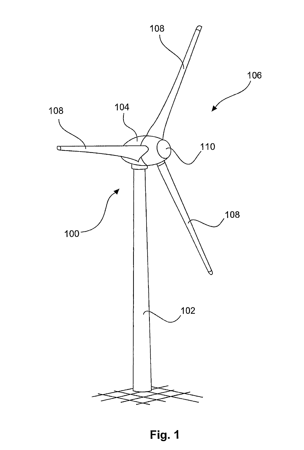
[0033]FIG. 1 shows a wind turbine 100, having a tower 102 and a nacelle 104. A rotor 106, having three rotor blades 108 and a spinner 110, is disposed on the nacelle 104. When in operation, the rotor 106 is put into a rotary motion by the wind, and thereby drives a generator in the nacelle 104.

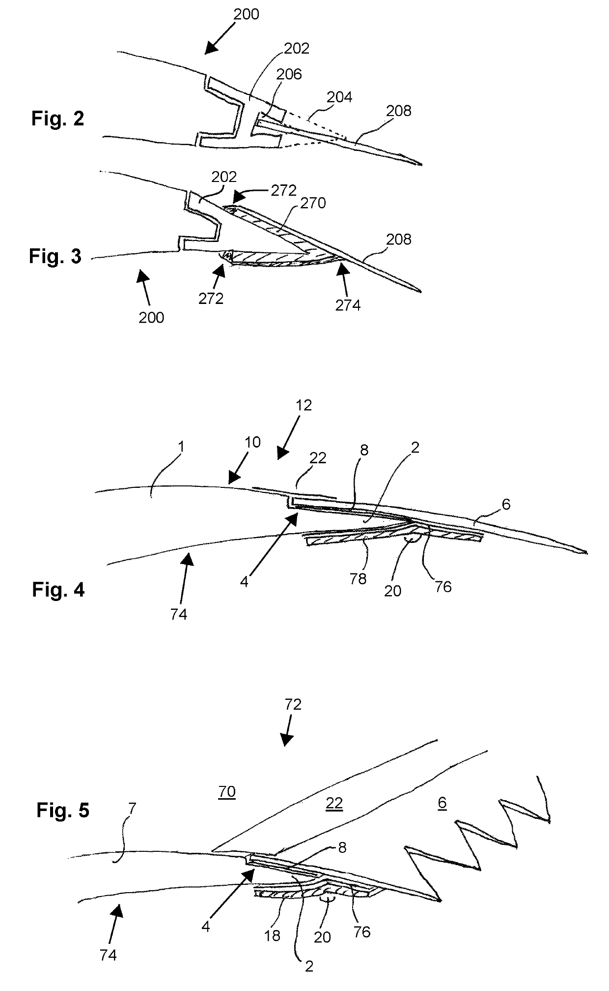
[0034]FIG. 2 shows a rear part of a rotor blade 200, having a mounted-on rear edge 202. FIG. 2 and, additionally, also FIGS. 3 and 4 show lateral sectional views, in which, for reasons of greater clarity, not all sectional surfaces are shown with hatching. The rear edge 202 originally tapered to a point, as the broken lines 204 are still intended to indicate. The rear edge 202 also had an interior cavity 206. For the purpose of attaching a serrated rear edge 208, the mounted-on edge 202 has been sawn open, such that the cavity 206 was made accessible. The serrated rear edge 208 could thus be inserted in the cavity 206 and attached there.

[0035]FIG. 3 shows a variant in which a rear edge 202 wit...


PUM


Abstract

A method for applying a serrated rear edge to a blade rear edge of a rotor blade of a wind turbine that has a pressure side and a suction side. The method comprises the steps: disposing the serrated rear edge, with an attaching portion, on a surface of the blade rear edge, and attaching the serrated rear edge, in the region of the attaching portion, to the rotor blade by means of adhesive, the serrated rear edge being disposed on the suction side and being additionally fixed by application of an overlapping material strip to the pressure side, and the material strip being disposed on the pressure side and on the serrated rear edge such that it overlaps a transition between the blade rear edge and the serrated rear edge, or the serrated rear edge being disposed on the pressure side and additionally fixed by application of an overlapping material strip to the suction side, and the material strip being disposed on the suction side and on the serrated rear edge such that it overlaps a transition between the blade rear edge and the serrated rear edge.

Description

BACKGROUND[0001]Technical Field[0002]The present invention relates to a method for applying a serrated rear edge to a blade rear edge of a rotor blade. The present invention additionally relates to such a serrated rear edge, and to a rotor blade having such a serrated rear edge. The invention also relates to a wind turbine having at least one rotor blade having a serrated rear edge.[0003]Description of the Related Art[0004]Serrated rear edges of rotor blades of wind turbines, especially so-called horizontal-axis wind turbines, are known. They are disposed at the blade rear edge of the rotor blade, at least in a portion, and then constitute there, essentially, the new rear edge of the rotor blade. This new rear edge, i.e., this serrated rear edge, thus creates a serrated contour, in particular having long, pointed serrations, which influences the aerodynamic behavior in this region. For such serrated rear edges, the term “serrations” is also generally used.[0005]It has been found tha...

Claims


Application Information

Patent Timeline
Patent Type & Authority Patents(United States)
IPC IPC(8): F03D1/06F03D13/10F03D80/30F03D1/00
CPCF03D1/0675F03D13/10F03D80/30Y02P70/523F05B2230/60Y02E10/721F05B2240/30F05B2260/30F05B2230/23F05B2260/96Y02E10/72Y02P70/50
Inventor KUHN, MARVIN
Owner WOBBEN PROPERTIES GMBH
Why Eureka
Try Eureka