Supercharge Your Innovation With Domain-Expert AI Agents!

Gas turbine nacelle ventilation manifold having a circumferential varying cross-sectional area

a technology of ventilation manifold and gas turbine, which is applied in the direction of efficient propulsion technology, mechanical equipment, machines/engines, etc., can solve the problems of volume tapped, uniform cooling load across the circumference of the interior of the nacelle, and reduce the efficiency or the amount of propulsion provided for a given amount of fuel being burned, so as to reduce the airflow

Active Publication Date: 2019-10-15
RTX CORP
View PDF29 Cites 1 Cited by
  • Summary
  • Abstract
  • Description
  • Claims
  • Application Information

AI Technical Summary

Benefits of technology

This design enhances propulsion efficiency by optimizing airflow distribution, ensuring adequate cooling for high heat load components during high power operations while conserving airflow during lower power conditions, thus improving overall engine performance and fuel efficiency.

Problems solved by technology

The cooling air moving inwardly of the nacelle may be tapped from the bypass flow and, thus, the volume tapped reduces the efficiency or amount of propulsion provided for a given amount of fuel being burned.
The cooling load is not uniform across a circumference of the interior of the nacelle.

Method used


Image

  • Gas turbine nacelle ventilation manifold having a circumferential varying cross-sectional area
  • Gas turbine nacelle ventilation manifold having a circumferential varying cross-sectional area

Examples


Embodiment Construction

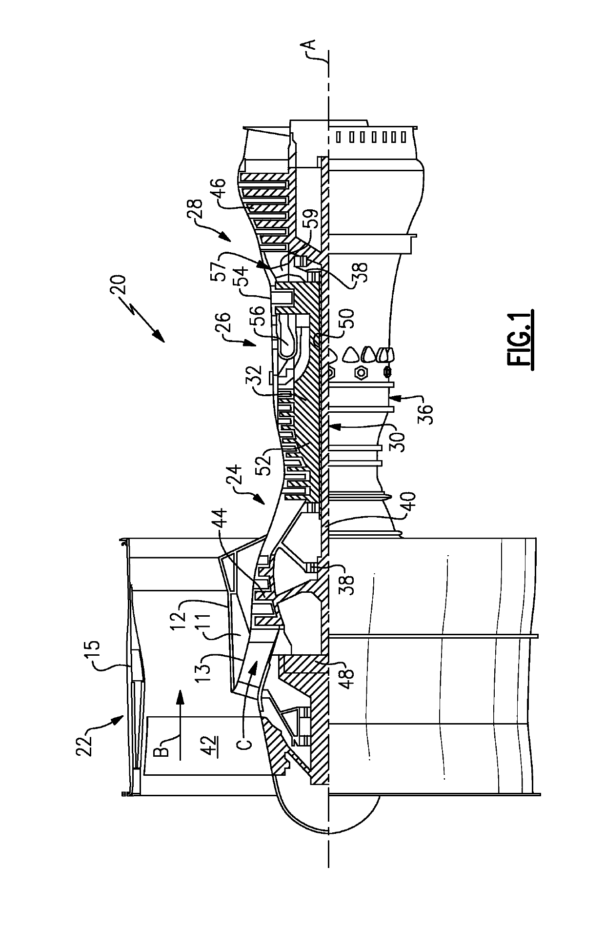
[0034]FIG. 1 schematically illustrates a gas turbine engine 20. The gas turbine engine 20 is disclosed herein as a two-spool turbofan that generally incorporates a fan section 22, a compressor section 24, a combustor section 26 and a turbine section 28. Alternative engines might include an augmentor section (not shown) among other systems or features. The fan section 22 drives air along a bypass flow path B in a bypass duct defined within a nacelle 15, while the compressor section 24 drives air along a core flow path C for compression and communication into the combustor section 26 then expansion through the turbine section 28. Although depicted as a two-spool turbofan gas turbine engine in the disclosed non-limiting embodiment, it should be understood that the concepts described herein are not limited to use with two-spool turbofans as the teachings may be applied to other types of turbine engines including three-spool architectures.

[0035]The exemplary engine 20 generally includes ...


PUM


Abstract

A gas turbine engine comprises a core engine housing. A nacelle is positioned radially outwardly of the core engine housing. An outer bypass housing is positioned outwardly of the nacelle. There is at least one accessory to be cooled positioned in a chamber radially between the core engine housing and the nacelle. A manifold delivers cooling air into the chamber, and extends ng circumferentially about a central axis of the core engine. The nacelle has an asymmetric flow cross-section across a circumferential extent.

Description

CROSS-REFERENCE TO RELATED APPLICATION[0001]This application claims priority to U.S. Provisional Patent Application No. 61 / 939,296, filed Feb. 13, 2014.BACKGROUND OF THE INVENTION[0002]This application relates to a ventilation manifold having a variable cross-sectional flow area across a circumference of an associated engine.[0003]Gas turbine engines are known and, typically, include a fan delivering air into a bypass duct. The bypass duct is defined outwardly of a core housing. The core housing has an upstream end, typically, known as a nacelle. Cooling air may be supplied within the core housing and across various accessories that are positioned within the core housing. As an example, various fluid components must be cooled. Also, an accessory gearbox may be positioned within the housing and must be cooled.[0004]An inner core housing houses a compressor, a combustor and a turbine section. The amount of air delivered into the bypass duct provides a propulsion flow in addition to an...

Claims


Application Information

Patent Timeline
Patent Type & Authority Patents(United States)
IPC IPC(8): F02C7/18F02C9/18F02C3/04F01D25/26F01D17/14
CPCF01D17/145F02C7/18F05D2260/608Y02T50/60F02C3/04F02C9/18
Inventor SUCIU, GABRIEL L.CHANDLER, JESSE M.PAPA, FEDERICO
Owner RTX CORP
Features
  • R&D
  • Intellectual Property
  • Life Sciences
  • Materials
  • Tech Scout
  • Unparalleled Data Quality
  • Higher Quality Content
  • 60% Fewer Hallucinations
Learn More