Supercharge Your Innovation With Domain-Expert AI Agents!

Method for beamforming a beam using an active antenna

a beamforming and active technology, applied in the direction of individually energised antenna arrays, polarised antenna unit combinations, polarisation/directional diversity, etc., can solve the problems of difficult and sometimes even impossible creation of wider beams with this conventional techniqu

Active Publication Date: 2019-10-15
TELEFON AB LM ERICSSON (PUBL)
View PDF6 Cites 1 Cited by
  • Summary
  • Abstract
  • Description
  • Claims
  • Application Information

AI Technical Summary

Benefits of technology

The present invention allows for the creation of beams with different shapes and widths, covering a large angle range. This is a feat that conventional beamforming cannot achieve.

Problems solved by technology

The market for active antennas with distributed radio chains in mobile telephony systems is very immature with only a small number of commercial products.
However, in many cases, creating wider beams are very difficult and sometimes even impossible with this conventional technique, using the power resource efficiently, as illustrated in connection with FIG. 3.

Method used


Image

  • Method for beamforming a beam using an active antenna
  • Method for beamforming a beam using an active antenna
  • Method for beamforming a beam using an active antenna

Examples


example 1

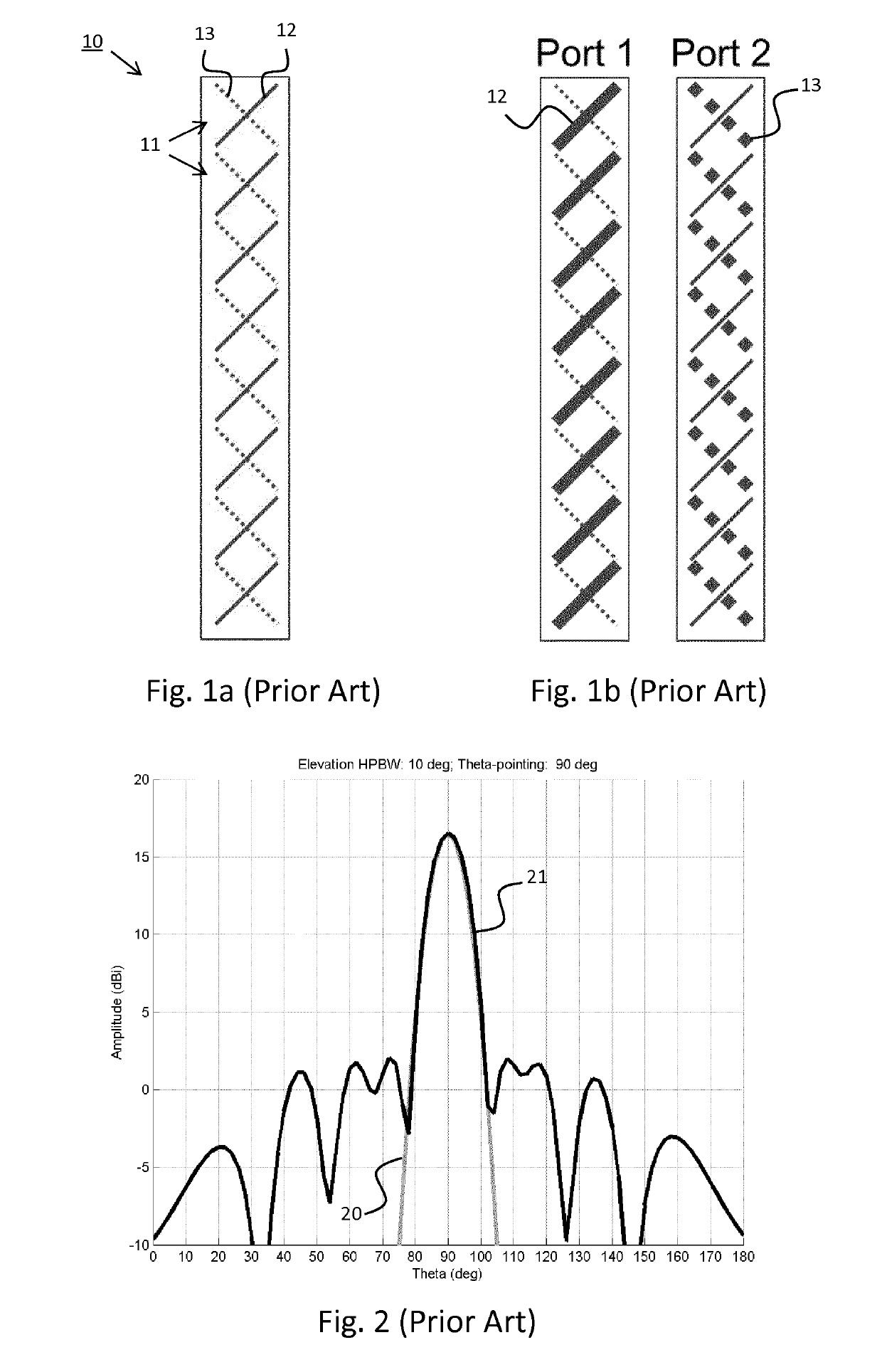
[0069]An antenna with 8 dual polarized subarrays, here with only 1 dual polarized element per subarray. BWreference (HPBW)=11 degrees when feeding all antenna subarrays with unit amplitude and zero phase.

[0070]Target beamwidth is 13 degrees HPBW, which means:

[0071]n=1113*8≈6.77=>BFindex=N-nN=8-6.778≈0.15<0.3

[0072]Therefore SPBF is selected with n=7, indicated by 7+0 (SPBF) in FIG. 11.

[0073]If beamforming index is ranging from 0.3-0.5 (0.3index<0.5) then single polarization beamforming using “n” first antenna subarrays or dual polarization beamforming using “n” first antenna subarrays and “N−n” second antenna subarrays is selected based upon which configuration gives as low sidelobes as possible

example 2

[0074]An antenna with 8 dual polarized subarrays, here with only 1 dual polarized element per subarray. BWreference (HPBW)=11 degrees.

[0075]Target beamwidth is 18 degrees HPBW, which means that for a one-dimensional antenna with 8 dual polarized antenna subarrays:

[0076]n=1118*8≈4.89=>BFindex=N-nN=8-4.898≈0.39>0.3⁢⁢and⁢<0.5

[0077]SPBF using n+0, i.e. 5+0, subarrays will result in a maximum sidelobe level of approximately −10 dB (FIG. 11), and DPBF using n+(N−n), i.e. 5+3, subarrays will result in a maximum sidelobe level of −11 dB (FIG. 12). Therefore, DPBF with 5+3 antenna subarrays is selected to be used.

example 3

[0078]An antenna with 8 dual polarized subarrays, here with only 1 dual polarized element per subarray. BWreference (HPBW)=11 degrees.

[0079]Target beamwidth is 17 degrees HPBW, which means that for a one-dimensional antenna with 8 dual polarized antenna subarrays:

[0080]n=1117*8≈5.18=>BFindex=N-nN=8-5.188≈0.35>0.3⁢⁢and⁢<0.5

[0081]SPBF using n+0, i.e. 5+0, subarrays will result in a maximum sidelobe level of approximately −12 dB (FIG. 11), and DPBF using n+(N−n), i.e. 5+3, subarrays will result in a maximum sidelobe level of −9 dB (FIG. 12). Therefore, SPBF with 5+0 antenna subarrays is selected to be used.

[0082]If beamforming index is in the order of, or larger than, 0.5 (BFindex≳0.5) then dual polarization beamforming using equal number of first antenna subarrays and second antenna subarrays is selected.


PUM


Abstract

The present invention relates to a method for beamforming a beam using an active antenna having predetermined aperture data predetermined aperture data comprising M×N dual polarized antenna subarrays within an aperture, each dual polarized antenna subarray comprising a first antenna subarray having a first polarization and a second antenna subarray having a second polarization non-parallel with the first polarization. The method comprises: selecting number of antenna ports, each antenna port being adapted to generate a separate beam using a combination from the first antenna subarray and / or the second antenna subarray; selecting port properties, comprising target beamwidth for each separate beam and desired polarization between beams; and determining port partitioning based upon aperture data and port properties for each antenna port, to adjust an effective length of the aperture over which the beam is created and thereby defining which first antenna subarray(s) and / or second antenna subarray(s) to use for each antenna port.

Description

CROSS-REFERENCE TO RELATED APPLICATION(S)[0001]This application is a 35 U.S.C. § 371 National Stage of International Patent Application No. PCT / EP2014 / 079202, filed Dec. 23, 2014, designating the United States, the disclosure of which is incorporated by reference.TECHNICAL FIELD[0002]The disclosure relates to a method for beamforming a beam as defined in the preamble of the independent claim 1. The invention also relates to an antenna system.BACKGROUND[0003]The market for active antennas with distributed radio chains in mobile telephony systems is very immature with only a small number of commercial products. Most active antenna arrays till now are related to testbeds.[0004]One of the properties an active antenna array is desired to have is flexibility to adjust port characteristics based on needs. One example of flexibility is the ability to adjust beamwidths within a wide angular interval and of course to steer the beam in different directions. It is also desired to use the availa...

Claims


Application Information

Patent Timeline
Patent Type & Authority Patents(United States)
IPC IPC(8): H01Q3/24H04B7/10H04B7/06H01Q21/26H01Q21/22H01Q3/26
CPCH01Q3/2605H01Q21/22H01Q21/26H04B7/0617H04B7/10H01Q3/247
Inventor PETERSSON, SVENJOHANNISSON, BJÖRNJOHANSSON, MARTIN
Owner TELEFON AB LM ERICSSON (PUBL)
Features
  • R&D
  • Intellectual Property
  • Life Sciences
  • Materials
  • Tech Scout
  • Unparalleled Data Quality
  • Higher Quality Content
  • 60% Fewer Hallucinations
Learn More