Cosmetic wiper with wiper arms

a technology of wiper arms and wipers, which is applied in the field of wipers, can solve the problems of limiting design options, conflicting objectives, and a lot of cosmetic mass in the bristle covering, and achieves the effect of balancing the actual applicator portion and the intensity of wiping

Active Publication Date: 2019-10-22
GEKA
View PDF20 Cites 9 Cited by
  • Summary
  • Abstract
  • Description
  • Claims
  • Application Information

AI Technical Summary

Benefits of technology

[0008]The invention is based on the object of creating a solution that provides a wiper in which the intensity of wiping and the resistance that the wiper puts up against the withdrawal of the applicator and the actual applicator portion are favorably balanced and, in particular, in which an operation from the outside is not necessary for achieving a change of the distal diameter of the wiper inside the applicator container.
[0012]In addition, this design provides the option of making the stem portion itself sufficiently elastic, so that it can be said that the respective ring portion is held at the free end of a leaf spring, which can be bent outwards in the radial direction to a more than just inconsiderable extent and is formed by the stem portion.
[0013]In this way, the characteristics of the wiper tend to become softer, i.e. the resistance it puts up against the bristle covering during withdrawal tends to become less, the bristle covering is treated gently. The danger that individual bristles buckle prematurely and are unable to straighten up again becomes significantly smaller. The wiper arms respond flexibly to cosmetics applicators of different sizes, i.e. cosmetics applicators that have different diameters in their applicator covering. Nevertheless, the wiping action is not too small, because the ring portion, due to the concave curvature which characterizes it and which its inner face has that radially faces towards the respectively associated applicator covering, still nestles up closely to the covering of the applicator and wipes it off with sufficient intensity. In this case, the extent of the wiping intensity can be controlled rather well, in a first approximation, through the smaller or greater spring elasticity of the respective stem portion onto which the respective ring portion is molded.
[0017]In order to ensure optimum performance, attention must be paid that the ring arms are not only indicated and in each case possibly protrude laterally over the stem portion only slightly, by an amount of possibly only one or even the fraction of a millimeter. According to the invention, the two ring arms together, viewed in the circumferential direction, preferably constitute at least 35%, better at least 50% of the length of the ring arms. This promotes the flexibility of the ring arms, i.e. the capacity at their outermost ends to be displaced, if possible, in the radially outward direction, under a load. For the ring arms are preferably configured with such an elasticity that they are able to be resilient in a radially outward direction relative to the stem portion and the part of the ring portion directly connected with it. Thus, the invention is also characterized in that the ring arms are so elastic that they are able to be resilient in a radially outward direction relative to the stem portion.
[0022]According to an embodiment of the invention, a design is preferably selected in which a window is enclosed by two adjacent ring portions, the associated stem portions and the retaining portion. Such a window substantially improves pressure compensation and thus contributes to preventing the dreaded “blob effect”. This refers to the effect that a considerable pumping action is produced when the applicator loaded with cosmetic mass is withdrawn from the cosmetics supply, which creates a significant negative pressure in the cosmetics storage container. At the instance the applicator leaves the cosmetics storage container, the internal pressure collapses abruptly, which produces said “blob” noise. This is critical in that cosmetic mass may squirt out due to the pressure surge, which is extremely undesirable due to the stain effect associated with this.
[0023]It was found to be particularly beneficial to have a projection protrude into the window, which is connected on its one side to the retaining portion and projects therefrom like a cantilever beam. Though this projection makes the free window surface area smaller, it creates an important guiding effect for the covering and, in particular in cosmetics applicators with injection-molded bristles, prevents the bristles from interacting with the window with such intensity that the danger of damage to them and / or their premature fatigue (bend recovery exhausted) looms. In another embodiment, the invention therefore provides that a projection, which is connected, preferably elastically, on its one side to the retaining portion and projects therefrom like a cantilever beam, protrudes into the window.

Problems solved by technology

A conflict of objectives is often the result especially if applicators with a bristle covering are used.
If the clear internal diameter of the wiper lip of such a wiper is dimensioned to be comparatively large, the wiper does not put up any excessive resistance to the withdrawal of the applicator, but leaves a lot of cosmetic mass in the bristle covering.
In many cases, this conflict of objectives leads to the necessity, with regard to the design of the applicator, of having to maintain a certain diameter ratio between the applicator stem and the core of the applicator carrying the bristles, which limits the design options.
This is disadvantageous in that the flexible wiper arm has to be operated from the outside.

Method used


Image

  • Cosmetic wiper with wiper arms
  • Cosmetic wiper with wiper arms
  • Cosmetic wiper with wiper arms

Examples


Embodiment Construction

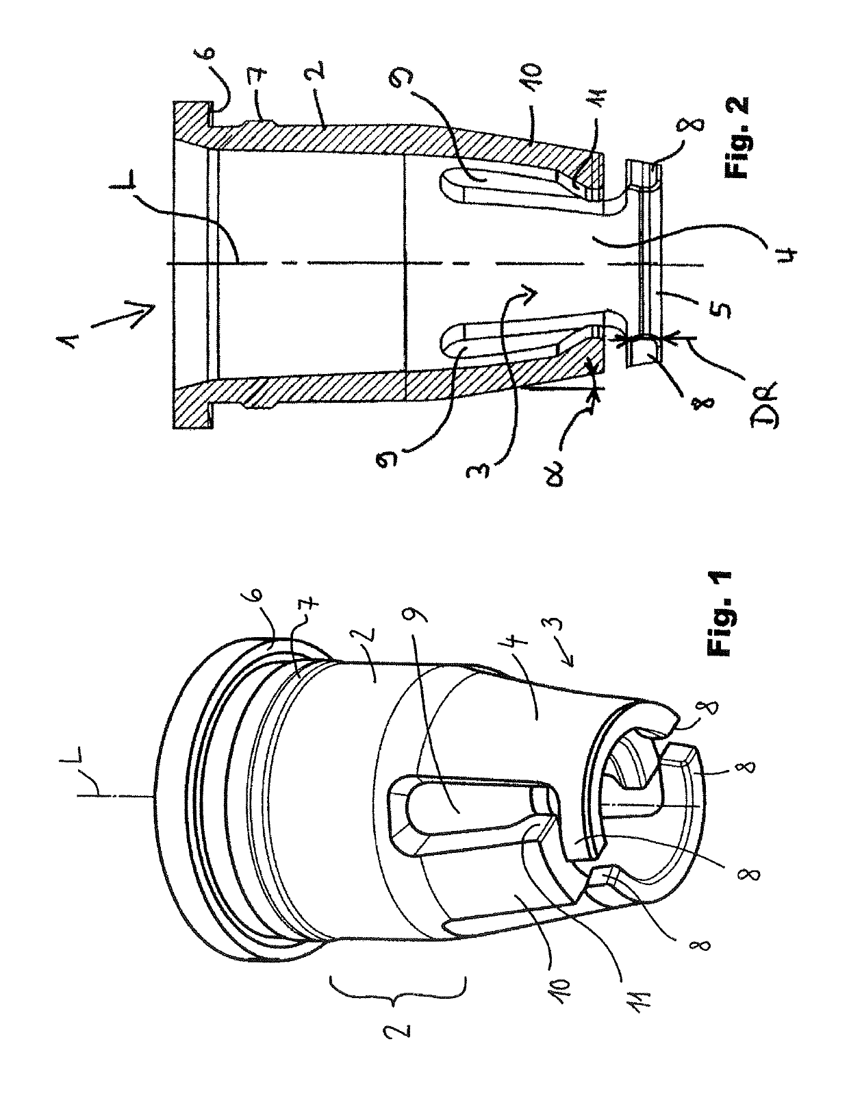
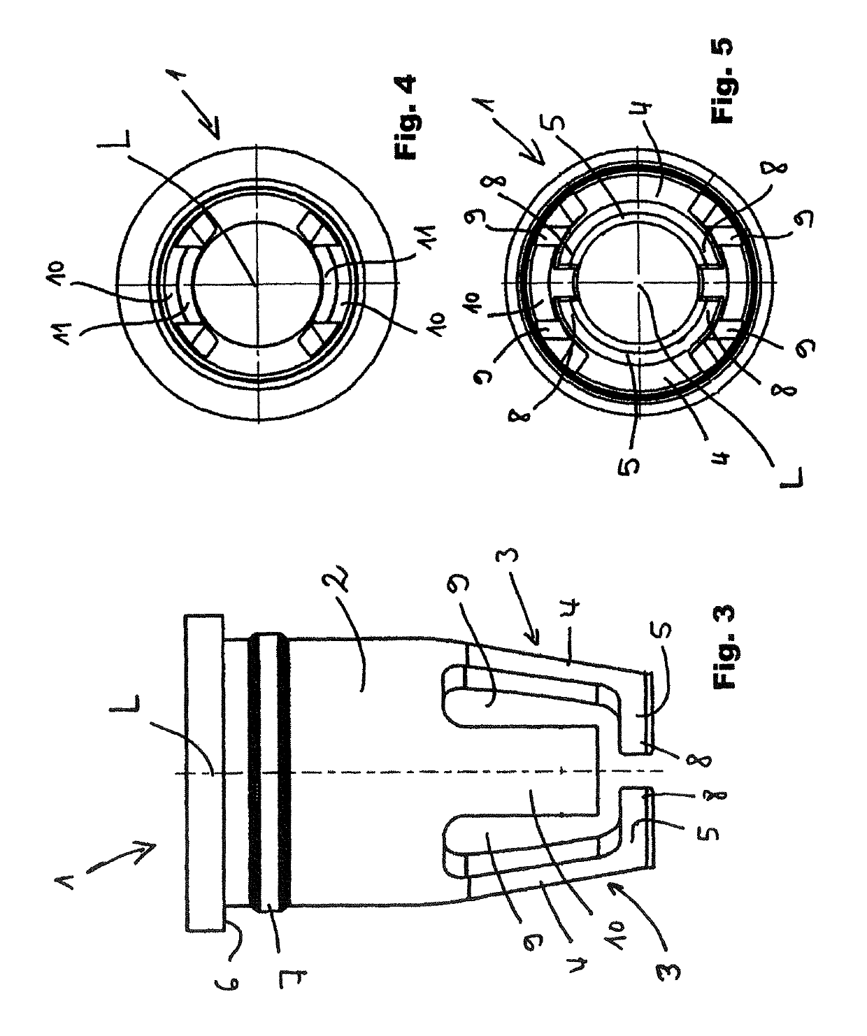
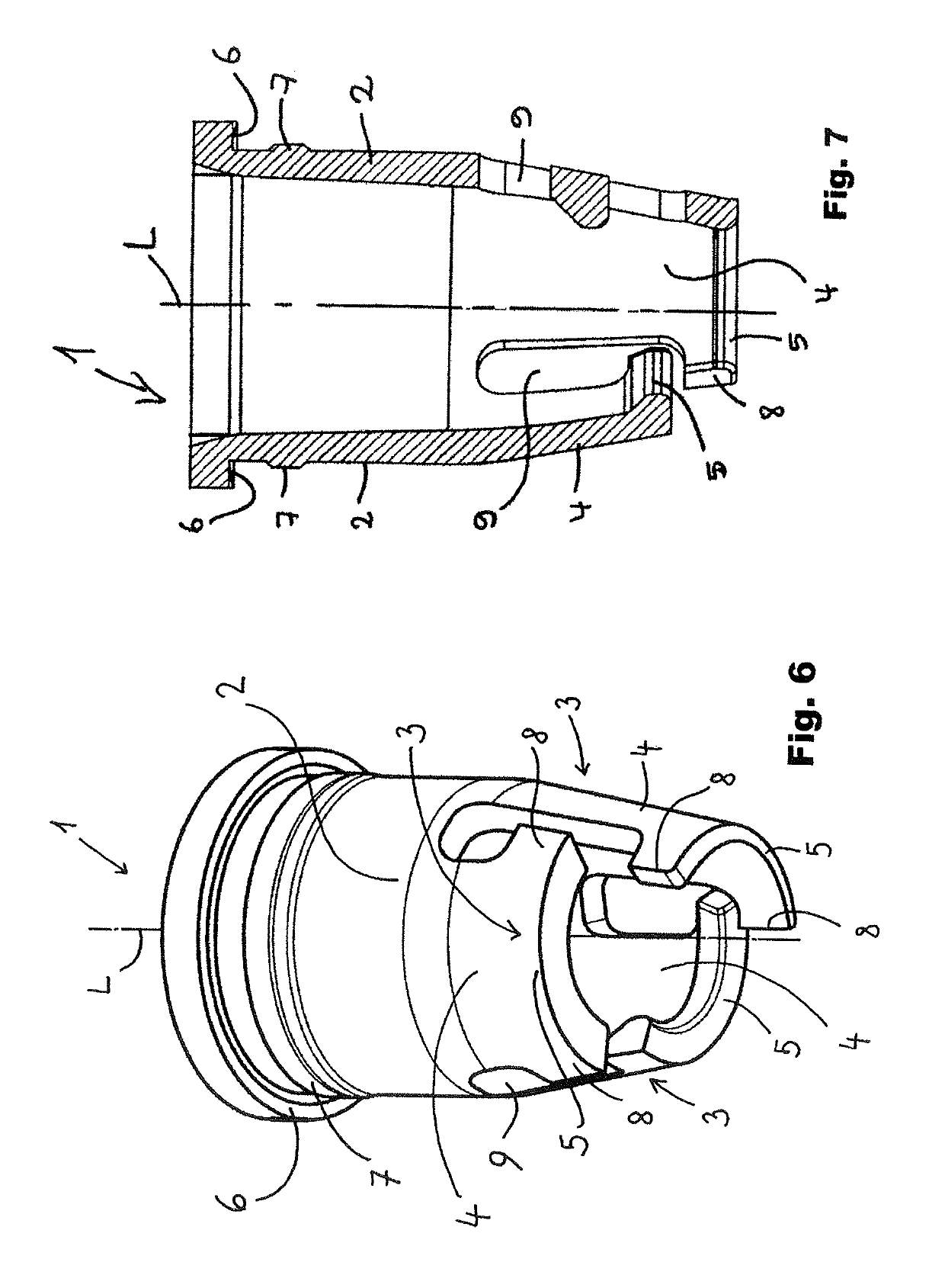
[0043]It has to be noted in advance that the wipers 1 according to the invention are preferably used as wipers for mascara mass. Ideally, each of the wipers 1 according to the invention forms a cosmetics unit 20 together with a cosmetics storage container 22 and a suitable cosmetics applicator 24 as well as a closure cap 26, as shown in FIG. 11. In this case, the wiper 1 according to the invention is inserted into the bottle neck or the container, removal opening in such, a way that its wiper arms protrude away from the container neck or the removal opening into the interior of the cosmetics storage container 22.

[0044]Then, it must be noted as generally valid that the term “distal” refers to the side of the wiper protruding the farthest into the interior of a cosmetics storage container in the longitudinal direction, whereas the term “proximal” refers to the side of the wiper closest in the longitudinal direction to the edge of the removal opening of the cosmetics container or cosme...


PUM


Abstract

A wiper for wiping an associated cosmetic applicator, wherein the wiper has a retaining portion for securing the wiper on a cosmetic supply container, and also has at least two wiper arms, which are arranged on the container and subject the associated cosmetic applicator to wiping action. Each of the at least two wiper arms is arranged in an elastically movable manner on the retaining portion and has a shaft portion and a ring portion, which forms a wiper lip or a part thereof, wherein the extent of the ring portion in the circumferential direction is greater than the extent of the shaft portion in the circumferential direction.

Description

FIELD OF THE INVENTION[0001]The invention is directed to a wiper, in particular to a wiper for wiping off a cosmetics applicator that can be associated with it, or is associated with it in the case of the wiper being used in a cosmetics storage container, wherein the wiper has a retaining portion for fixing the wiper to a cosmetics storage container and at least two wiper arms that are disposed on the retaining portion and exert a wiping action on the associated cosmetics applicator.BACKGROUND OF THE INVENTION[0002]Such a wiper serves for wiping off excess cosmetic mass from an applicator that is dipped into a cosmetic mass stored in a cosmetics storage container and is then withdrawn from the cosmetics storage container through the wiper, in order to apply a certain amount of the cosmetic, preferably without any dripping, with the cosmetics applicator then loaded with cosmetic mass. In particular, the invention relates to a wiper for lip gloss mass or mascara mass applicators. Gene...

Claims


Application Information

Patent Timeline
Patent Type & Authority Patents(United States)
IPC IPC(8): A45D34/04A45D40/26
CPCA45D40/267A45D34/046
Inventor WEIGEL, FRIEDRICH
Owner GEKA
Why Eureka
Try Eureka