Liquid ejecting apparatus driving method, and liquid ejecting apparatus
a technology of liquid ejecting apparatus and driving method, which is applied in the direction of printing, other printing apparatus, etc., can solve the problems of deteriorating performance of difficult or even impossible function recovery of defective nozzles, and the risk of so-called defective nozzle phenomenon, etc., to achieve the effect of suppressing the deterioration of recovery performan
- Summary
- Abstract
- Description
- Claims
- Application Information
AI Technical Summary
Benefits of technology
Problems solved by technology
Method used
Image

Examples
first embodiment
[0061]In wiping operation performed by the printer 1 having the structure described above, among the four nozzle surface regions 34a to 34d, only a nozzle surface region(s) in which a defective nozzle(s) has been found is wiped. Assume a case where, for example, a defective nozzle N is found in the nozzle surface region 34c in the process of nozzle inspection (step S6). In this case, the wiper 54c only, which corresponds to the nozzle surface region 34c, is moved to wipe the nozzle surface region 34c only. Specifically, the wiping mechanism 7′ is activated so as to move the wipers 54a to 54d to a position where they are able to be brought into contact with the nozzle surface regions 34a to 34d of the recording head 2. Before this operation, the maintenance liquid supply unit 55 was activated to supply maintenance liquid to the wiper 54c only. In this state, the wiper 54c is moved in the direction of the nozzle lines (see the broken-line arrow in FIG. 8). Therefore, it is possible to...
third embodiment
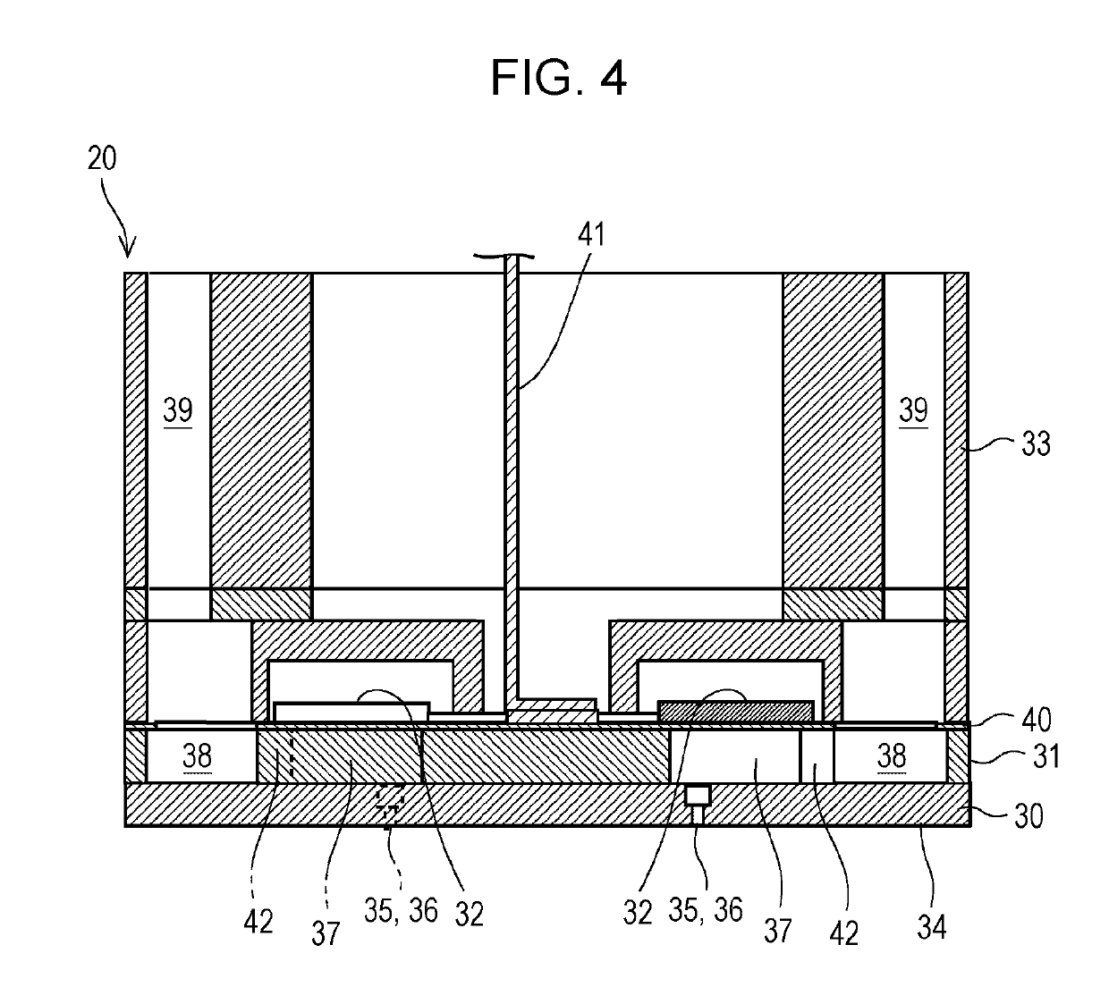
[0064]In the third embodiment, the wipers 54a to 54d, each as an individual wiper, are provided respectively for the nozzle surface regions 34a to 34d so as to be able to wipe the nozzle surface regions 34a to 34d independently of one another. However, the scope of the disclosure is not limited to the foregoing example. For example, an individual wiper may be provided for each of nozzle lines 36 so that the nozzle lines 36 will be able to be wiped independently of one another. In the embodiments described above, the piezoelectric element 32 that is a so-called deflection-vibration-mode element is described as an example of an actuator that gives rise to a pressure change in the ink inside the pressure compartment 37. However, the scope of the disclosure is not limited to the foregoing example. Various kinds of actuator can be adopted, for example, a so-called longitudinal-vibration piezoelectric element, a heat generation element, or an electrostatic actuator, which changes the capa...
PUM
 Abstract
Description
Claims
Application Information
 - R&D
- Intellectual Property
- Life Sciences
- Materials
- Tech Scout
- Unparalleled Data Quality
- Higher Quality Content
- 60% Fewer Hallucinations
Browse by: Latest US Patents, China's latest patents, Technical Efficacy Thesaurus, Application Domain, Technology Topic, Popular Technical Reports.
© 2025 PatSnap. All rights reserved.Legal|Privacy policy|Modern Slavery Act Transparency Statement|Sitemap|About US| Contact US: help@patsnap.com