
Radar data collection and labeling for machine learning

a technology of machine learning and data collection, applied in the field ofradar processing systems and methods, can solve the problems of difficult identification of objects represented by doppler measurements, and laborious manual collection and labeling of many such stored representations

Active Publication Date: 2019-10-22
PLATO SYST INC
View PDF7 Cites 26 Cited by
  • Summary
  • Abstract
  • Description
  • Claims
  • Application Information

AI Technical Summary

Benefits of technology

The patent relates to a system and method for processing radar data to provide information about objects in images captured by computer vision devices. The system uses machine learning to associate and label objects in the images with radar tracks, which can then be used in applications such as autonomous vehicles. The technical effects of the patent include improved accuracy and efficiency in identifying objects and their movement using radar and machine learning techniques.

Problems solved by technology

However, identifying objects represented by these measurements may be challenging.
However, identifying objects represented by the Doppler measurements may be challenging.
However, manually collecting and labeling many such stored representations may be tedious and expensive (in terms of human effort), and may not provide a diverse enough representation for reliable inference.
Two common types of problems in machine learning are classification problems and regression problems.
Each model develops a rule or algorithm over several epochs by varying the values of one or more variables affecting the inputs to more closely map to a desired result, but as the training dataset may be varied, and is preferably very large, perfect accuracy and precision may not be achievable.
When performing analysis of complex data, one of the major problems stems from the number of variables involved.
Analysis with a large number of variables generally requires a large amount of memory and computational power, and it may cause a classification algorithm to overfit to training samples and generalize poorly to new samples.
The challenge is that for a typical neural network, there may be millions of parameters to be optimized.
Trying to optimize all these parameters from scratch may take hours, days, or even weeks, depending on the amount of computing resources available and the amount of data in the training set.
In general, however, such mathematical models are difficult to develop.
In contrast, radar data is not easily interpreted by a human looking at the data in general.
While it is possible to develop a user interface which allows a human to discern a moving object after appropriate radar processing, it is difficult for a human to label the object (e.g., human versus dog).
More importantly, while humans can naturally draw bounding boxes around salient objects in an image and label them, it is not possible to draw similar bounding boxes around radar data.
The data is complex-valued, and does not always have a natural visualization.
Devising a user interface for humans to label such data is therefore difficult.
However, at shorter ranges, computer vision may be able to resolve objects that a radar tracker cannot.
Poor lighting conditions include night and poor weather, but the quality of vision can also be degraded in daytime conditions, such as due to shadows.
Radar, on the other hand, is insensitive to lighting conditions.
The label information provided by the computer vision system can be unreliable when the objects being detected are at a large distance (i.e., when they occupy a small number of pixels in the image).
However, in some cases, the computing machine may be uncertain, and probabilistic (rather than determinate) labeling may be used, as described in greater detail below.
The labels output by the computer vision system may be noisy, hence the obtained labels may be averaged across several time slots along a trajectory.

Method used


Image

  • Radar data collection and labeling for machine learning
  • Radar data collection and labeling for machine learning
  • Radar data collection and labeling for machine learning

Examples


Embodiment Construction

[0028]The following description and the drawings sufficiently illustrate specific embodiments to enable those skilled in the art to practice them. Other embodiments may incorporate structural, logical, electrical, process, and other changes. Portions and features of some embodiments may be included in, or substituted for, those of other embodiments. Embodiments set forth in the claims encompass all available equivalents of those claims.

[0029]As discussed above, radar units output radar tracks that include range, Doppler, and / or micro-Doppler measurements. However, identifying objects represented by the Doppler measurements may be challenging. Some aspects of the technology described herein provide techniques for identifying objects represented by the Doppler measurements.

[0030]According to some schemes, representations of some common items (e.g., car, motorcycle, etc.), in terms of radar data, are collected and are stored in the memory of a computing machine. The computing machine t...


PUM


Abstract

Systems and methods for labeling radar tracks for machine learning are disclosed. According to some aspects, a machine accesses data from radar unit(s), the data from the radar unit(s) comprising radar tracks, each radar track comprising one or more of the following: Doppler and micro-Doppler measurement(s), range measurement(s), and angle measurement(s). The machine accesses data from computer vision device(s), the data from the computer vision device(s) comprising image(s), the data from the computer vision device(s) being associated with a common geographic region and a common time period with the data from the radar unit(s). The machine labels, using an image recognition module, objects in the image(s). The machine determines, based on the common geographic region and the common time period, that labeled object(s) in the image(s) map to radar track(s). The machine labels the radar track(s) based on labels of the labeled objects.

Description

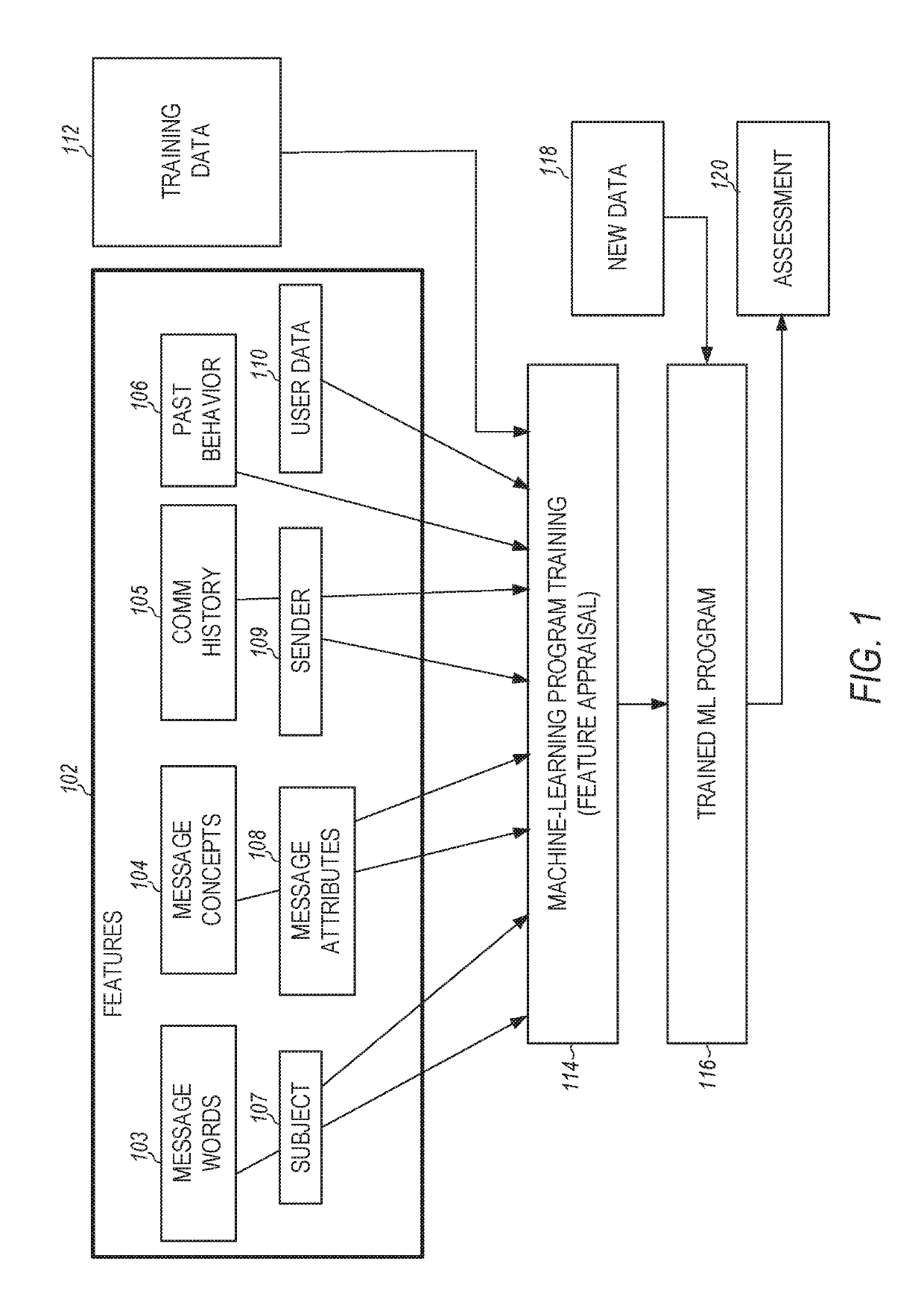
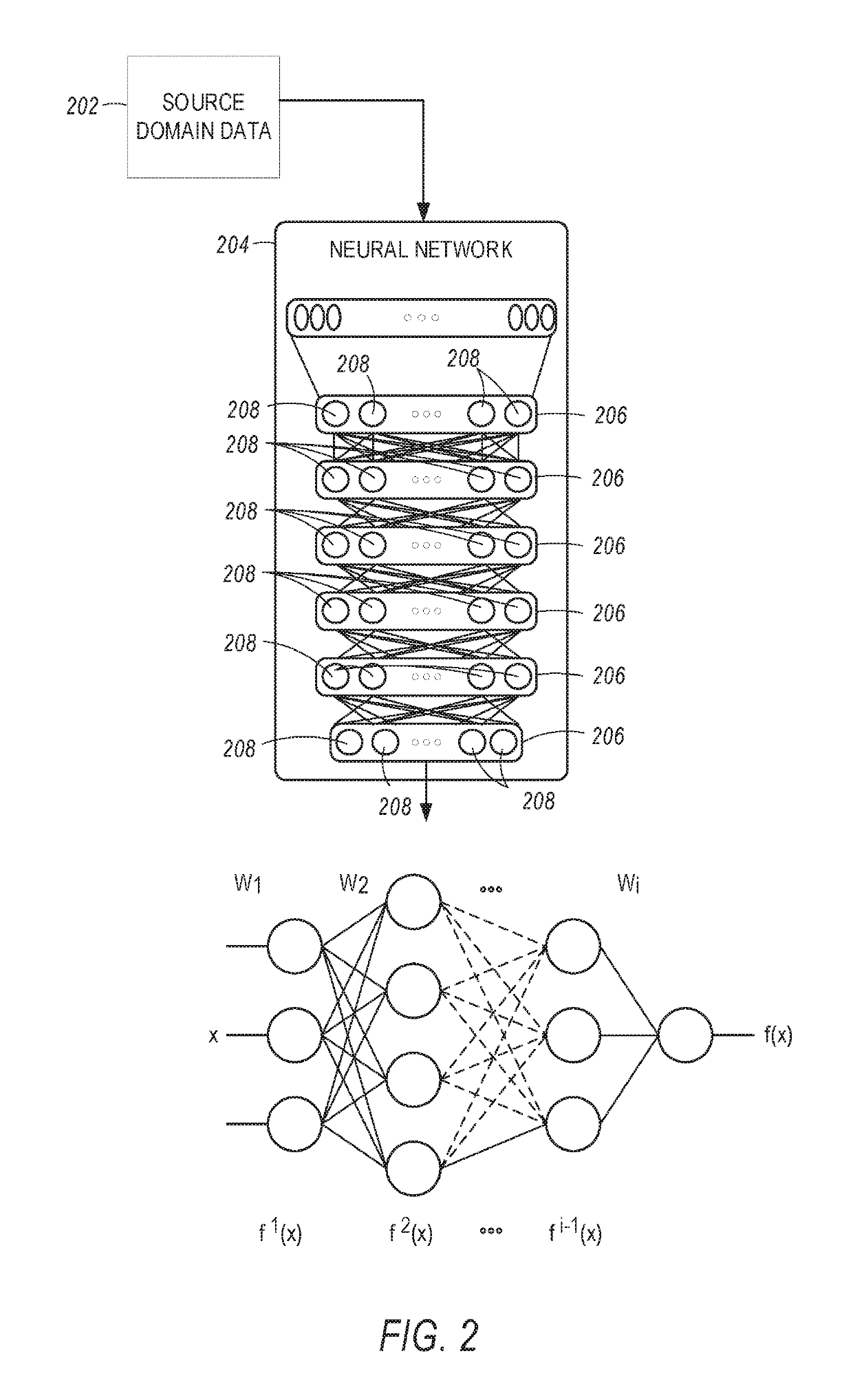
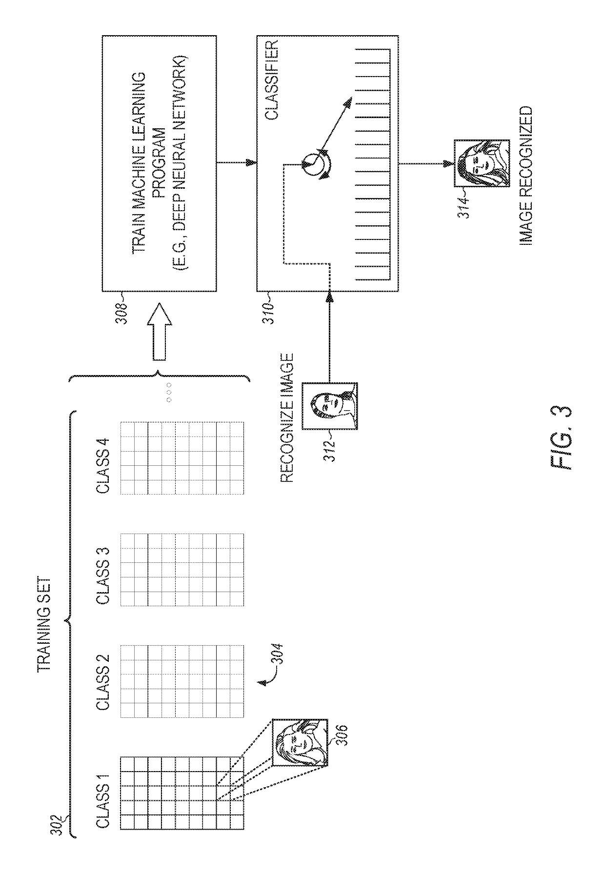
TECHNICAL FIELD[0001]Embodiments pertain to radar processing systems and methods. Some embodiments relate to labeling radar tracks for machine learning.BACKGROUND[0002]Radar units output radar tracks that include range-Doppler silhouettes and micro-Doppler measurements. However, identifying objects represented by these measurements may be challenging.BRIEF DESCRIPTION OF THE DRAWINGS[0003]FIG. 1 illustrates the training and use of a machine-learning program, in accordance with some embodiments.[0004]FIG. 2 illustrates an example neural network, in accordance with some embodiments.[0005]FIG. 3 illustrates the training of an image recognition machine learning program, in accordance with some embodiments.[0006]FIG. 4 illustrates the feature-extraction process and classifier training, in accordance with some embodiments.[0007]FIG. 5 is a block diagram of a computing machine, in accordance with some embodiments.[0008]FIG. 6 illustrates an example system in which labeling radar tracks for...

Claims


Application Information

Patent Timeline
Patent Type & Authority Patents(United States)
IPC IPC(8): G01S7/41G01S13/86G01S13/72
CPCG01S13/867G01S7/417G01S13/723
Inventor MADHOW, UPAMANYUARBABIAN, MOHAMMAD AMINMAMANDIPOOR, BABAKNAN, HAO
Owner PLATO SYST INC
Learn More