Image processing system and method for interactive contouring of three-dimensional medical data

a three-dimensional, interactive technology, applied in image data processing, instruments, computing, etc., can solve the problems of one of the most tedious and time-consuming parts of radiotherapy planning, and achieve the effect of improving geometrical interpolation and low degree of manual intervention

Active Publication Date: 2019-10-22
RAYSEARCH LAB
View PDF5 Cites 2 Cited by
  • Summary
  • Abstract
  • Description
  • Claims
  • Application Information

AI Technical Summary

Benefits of technology

[0008]The object of the present invention is therefore to offer a solution which, on one hand, requires a relatively low degree of manual intervention; and, on the other hand, provides an improved geometrical interpolation in a three-dimensional image data set.
[0010]This arrangement is advantageous because the joint use of the first and second edges and the source data enables reaching a high-quality delineation of the anatomic structure of interest in relatively few discrete steps. Other advantages are that no contour libraries are required. Further, the different subsets of source data need not be especially similar to one another. In other words, the image slices can be separated by a relatively large distance. Of course, this makes the solution highly flexible from a user perspective.
[0013]Thus, preferably, the processing unit is configured to calculate a first subsequent estimate of the three-dimensional shell based on the initial estimate of the three-dimensional shell and the source data. Any subsequent estimates thereafter are calculated based on the previous estimate of the three-dimensional shell, the first and second edges and the source data. Thereby, the estimate of the three-dimensional shell is held geometrically close both to the manually drawn contours and the image data, which vouches for an end result of high-quality.
[0014]According to yet another embodiment of this aspect of the invention, the processing unit is further configured to analyze a first data portion of the first subset of the source data in proximity to the first edge, and analyze a second data portion of the second subset of the source data in proximity to the second edge. Based on these analyses, in turn, the processing unit is configured to derive a set of image features defining an estimated perimeter of the anatomic structure of interest, and calculate the subsequent estimate of the three-dimensional shell on the further basis of the set of image features, e.g. using interpolation based on harmonic functions, where the set of image features represent boundary conditions for the interpolation process. Consequently, although the character of the image features may vary considerably over the surface around the structure of interest, its perimeter can be estimated accurately. For example, this approach renders it relatively unproblematic to delineate a femoral head whose bone structure may have very strong edges at some parts of the structure and very weak at other parts (where instead the surrounding structures may have very strong edges).
[0015]According to still another embodiment of this aspect of the invention, the processing unit is configured to generate a first iteration of a triangular mesh structure approximating the three-dimensional shell to the estimated perimeter. The triangular mesh structure includes a set of vertices each in which a number of triangles of the mesh structure meet. Preferably, the processing unit is further configured to generate at least one further iteration of the triangular mesh structure in addition to the first iteration, where the at least one further iteration of the triangular mesh structure represents an approximation of the estimated perimeter that is an improvement relative to the first iteration with respect to an overall distance measure between the estimated perimeter and the vertices of the triangular mesh structure. Hence, the perimeter of the anatomic structure of interest can be expressed accurately through the triangular mesh structure, which enables efficient graphical processing and visualization.
[0016]According to one further embodiment of this aspect of the invention, the processing unit is configured to select at least one further subset of the source data in addition to the first and second subsets. The at least one further subset defines at least one further two-dimensional graphic representation of the source data arranged in at least one further image slice through the anatomic structure of interest at at least one further axial position in the source data. The at least one further axial position is different from the first and second axial positions. For each of the at least one further subset, the processing unit is configured to generate control instructions configured to cause the second interface to output the at least one further subset of the source data for presentation on the graphical display. Then, in response to at least one further set of instructions received via the third interface, the processing unit is configured identify at least one further edge of the anatomic structure of interest in the at least one further image slice. Subsequently, based on the first, second and at least one further edges and the source data, where the processing unit is configured to calculate an improved version of the three-dimensional shell representing a surface estimate of the anatomic structure of interest. This means that the user can conveniently assist and speed up the automatic delineation process by adding one or more manually drawn contours.

Problems solved by technology

The process of defining which voxels that represent a particular anatomic structure, or so-called organ delineation, is one of the most tedious and time-consuming parts of radiotherapy planning.

Method used


Image

  • Image processing system and method for interactive contouring of three-dimensional medical data
  • Image processing system and method for interactive contouring of three-dimensional medical data
  • Image processing system and method for interactive contouring of three-dimensional medical data

Examples


Embodiment Construction

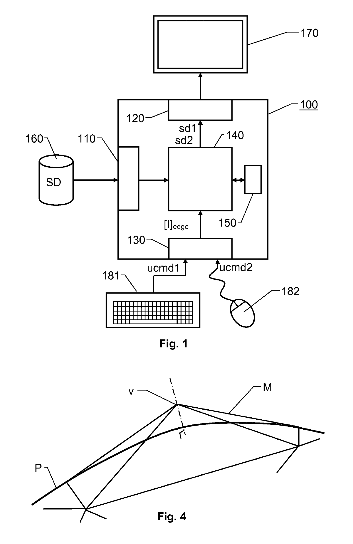
[0031]FIG. 1 shows an overview of an image processing system 100 for contouring three-dimensional medical image data according to one embodiment of the invention. The system 100 includes a processing unit 140 plus first, second and third interfaces 110, 120 and 130 respectively. Preferably, a memory 150 is also included, which stores software for executing the below-described procedure when the software is being run on the processing unit 140. For presentation purposes, FIG. 1 illustrates the interfaces 110, 120 and 130 as separate entities. However, in a practical implementation, two or more of the interfaces may be integrated into a common unit.

[0032]The first interface 110 is configured to enable the processing unit 140 access to source data SD in the form of three-dimensional medical image data that represent an anatomic structure of interest. The source data SD also contains tissues adjoining the anatomic structure of interest. The purpose of the proposed system 100 is to conto...


PUM


Abstract

An anatomic structure of interest is contoured in 3D source data by selecting a first subset of data in a first image slice at a first axial position (z1). A first set of instructions identifies a first edge (E1) of the anatomic structure of interest in the first image slice. Then, a second subset of data is selected in a second image slice at a second axial position (z2); and a second set of instructions identifies a second edge (E2) of the anatomic structure of interest in the second image slice. A three-dimensional shell (3DS) is calculated based on the first and second edges (E1; E2) and the source data (SD). The three-dimensional shell (3DS) represents an approximation of a delimiting surface that separates the anatomic structure of interest from adjoining tissues in the 3D source data.

Description

[0001]This application is the National Stage of International Application No. PCT / EP2017 / 072135, filed Sep. 4, 2017, and claims benefit of European Patent Application No. 16187218.9, filed Sep. 5, 2016, the entire contents of which are incorporated by reference herein.THE BACKGROUND OF THE INVENTION AND PRIOR ART[0002]The present invention relates generally to solutions for enhancing the information contents of medical image data. More particularly the invention relates to an image processing system according to the preamble of claim 1 and a corresponding method. The invention also relates to a computer program and a processor-readable medium.[0003]The process of defining which voxels that represent a particular anatomic structure, or so-called organ delineation, is one of the most tedious and time-consuming parts of radiotherapy planning. This process usually involves manual contouring in two-dimensional slices using simple drawing tools, and it may take several hours to delineate ...

Claims


Application Information

Patent Timeline
Patent Type & Authority Patents(United States)
IPC IPC(8): G06T7/12G06T7/149
CPCG06T7/12G06T7/149G06T2207/10072G06T2207/20096G06T2207/30004G06T7/174
Inventor WEISTRAND, OLA
Owner RAYSEARCH LAB
Why Eureka
Try Eureka