Techniques for selecting an antenna sub-array at a user equipment

a technology of user equipment and antenna sub-array, which is applied in the field of wireless communication systems to achieve the effects of reducing the acquisition time of network associated data, reducing the acquisition time, and increasing the reliability

Active Publication Date: 2019-10-22
QUALCOMM INC
View PDF7 Cites 0 Cited by
  • Summary
  • Abstract
  • Description
  • Claims
  • Application Information

AI Technical Summary

Benefits of technology

[0006]In some cases, a UE configured for mmW communication may include a plurality of antenna sub-arrays (e.g., a plurality of separate panels of antenna elements), with one of the antenna sub-arrays being connectable to a radio frequency (RF) chain of the UE at a time. When performing an initial acquisition procedure, the UE may connect a first of its antenna sub-arrays to an RF chain, measure at least one signal (e.g., signals on a plurality of directional beams) received from a base station, and determine whether the at least one signal measurement satisfies a threshold. If the UE successively connects each of its antenna sub-arrays to the RF chain and performs signal measurements for each antenna sub-array, the “acquisition time” for acquiring a network associated with the base station may be fairly long. On the other hand, if the UE only acquires measurements for a subset of its antenna sub-arrays, or stops acquiring measurements when it identifies a measurement satisfying a threshold, the UE may communicate with the base station using an antenna sub-array that is less than optimal. Techniques described in the present disclosure enable a UE to balance the tradeoff between shorter acquisition time and greater reliability by performing an initial acquisition procedure with a base station using each antenna sub-array of a first subset of antenna sub-arrays, selecting an antenna from the first subset for performing a random access procedure, and then selectively measuring at least one signal received from the base station for the purpose of determining whether a different antenna sub-array should be selected for communication with the base station.

Problems solved by technology

On the other hand, if the UE only acquires measurements for a subset of its antenna sub-arrays, or stops acquiring measurements when it identifies a measurement satisfying a threshold, the UE may communicate with the base station using an antenna sub-array that is less than optimal.

Method used


Image

  • Techniques for selecting an antenna sub-array at a user equipment
  • Techniques for selecting an antenna sub-array at a user equipment
  • Techniques for selecting an antenna sub-array at a user equipment

Examples


Embodiment Construction

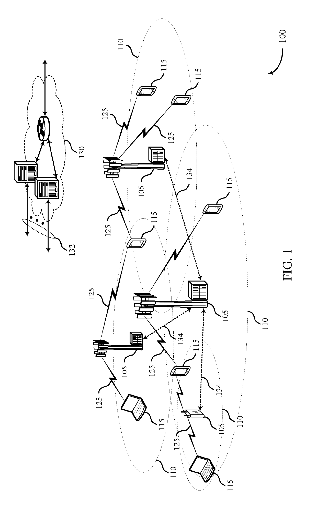
[0043]A wireless communication system (e.g., a mmW system) may utilize directional or beamformed transmissions (e.g., beams) for communication. For example, a base station may transmit signals on multiple beams associated with different directions. In some cases, the base station may engage in beam sweeping over a portion (or all) of the possible beams for transmitting messages or signals intended for UEs distributed throughout a coverage area of the base station. For example, a base station may transmit a discovery reference signal (DRS), synchronization channel, measurement reference signal (MRS), beam training sequence (BTS), or other signal on a plurality of beams. A UE that receives one of these signals may acquire a network associated with the base station. Techniques described in the present disclosure may be used to select an antenna sub-array at a UE for communicating with a base station.

[0044]The following description provides examples, and is not limiting of the scope, ap...


PUM


Abstract

Techniques are described for wireless communication at a user equipment (UE) having a plurality of antenna sub-arrays. One method includes performing an initial acquisition procedure with a base station using each antenna sub-array of a first subset of antenna sub-arrays, in which the first subset includes two or more antenna sub-arrays of the plurality of antenna sub-arrays; selecting an antenna sub-array from the first subset; and performing a random access procedure with the base station using the selected antenna sub-array. Another method includes performing a random access procedure with a base station using a first antenna sub-array in the plurality of antenna sub-arrays; selecting a second antenna sub-array in the plurality of antenna sub-arrays to use for communication with the base station after performing the random access procedure; and transmitting to the base station, on a beam, a scheduling request state indicating the selected second antenna sub-array.

Description

CROSS REFERENCES[0001]The present Application for Patent claims priority to U.S. Provisional Patent Application No. 62 / 476,464 by Chendamarai Kannan et al., entitled “Techniques For Selecting an Antenna Sub-Array At A User Equipment,” filed Mar. 24, 2017, assigned to the assignee hereof and incorporated by reference in its entirety.BACKGROUNDField of the Disclosure[0002]The present disclosure, for example, relates to wireless communication systems, and more particularly to techniques for selecting an antenna sub-array at a user equipment (UE).Description of Related Art[0003]Wireless communication systems are widely deployed to provide various types of communication content such as voice, video, packet data, messaging, broadcast, and so on. These systems may be multiple-access systems capable of supporting communication with multiple users by sharing the available system resources (e.g., time, frequency, and power). Examples of such multiple-access systems include code-division multi...

Claims


Application Information

Patent Timeline
Patent Type & Authority Patents(United States)
IPC IPC(8): H04L5/12H04B7/08H04B7/06H04W72/04H04W74/08
CPCH04B7/0811H04B7/082H04B7/0691H04B7/0868H04W74/0833H04W72/046
Inventor CHENDAMARAI KANNAN, ARUMUGAMLUO, TAO
Owner QUALCOMM INC
Why Eureka
Try Eureka