Linear array antenna simultaneous MIMO-SAR imaging system and method

A MIMO-SAR and linear array technology, applied in the field of linear array antenna simultaneous MIMO-SAR imaging system, can solve the problems of low system image refresh rate, complex imaging processing and motion compensation, unfavorable large-width imaging, etc.

Active Publication Date: 2015-01-07
FUZHOU TELEWARE ELECTRONICS
View PDF3 Cites 16 Cited by
  • Summary
  • Abstract
  • Description
  • Claims
  • Application Information

AI Technical Summary

Problems solved by technology

First of all, under the same working conditions, the time-sharing transmission and reception method needs to increase the pulse repetition frequency of the system, thereby reducing the unambiguous imaging distance of the system, which is not conducive to the realization of large-width imaging; secondly, due to the influence of platform movement, time-sharing transmission and reception makes conventional data The acquisition mode "go-stop-go" is no longer established, which causes the complexity of imaging processing and motion compensation; finally, due to the use of microwave switch networks for time-sharing single-send and single-receive or single-send and multiple-receive working methods, the time for a single data acquisition Longer, the system image refresh rate is relatively small

Method used


Image

  • Linear array antenna simultaneous MIMO-SAR imaging system and method
  • Linear array antenna simultaneous MIMO-SAR imaging system and method
  • Linear array antenna simultaneous MIMO-SAR imaging system and method

Examples


Embodiment Construction

[0035] Specific embodiments of the present invention will be described in detail below in conjunction with the accompanying drawings. It should be understood that the specific embodiments described here are only used to illustrate and explain the present invention, and are not intended to limit the present invention.

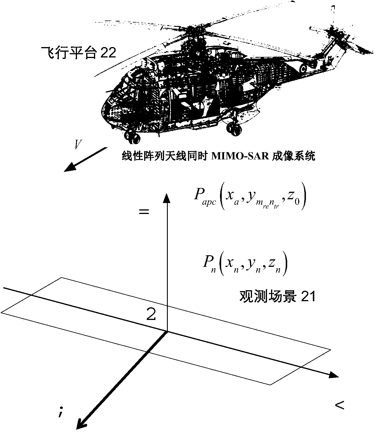
[0036] figure 1 It shows an example platform where the linear array antenna orthogonal frequency division MIMO-SAR transceiver device and the linear array antenna simultaneous MIMO-SAR imaging system provided by the present invention are applied. Such as figure 1 As shown, the linear array antenna orthogonal frequency division MIMO-SAR transceiver device and the linear array antenna simultaneous MIMO-SAR imaging system provided by the present invention can be installed on the belly of the flight platform 22 and move with the aircraft platform 22 . The imaging system generates multiple radio frequency signals through the MIMO-SAR transceiver device, and simulta...


PUM


Abstract

The invention discloses a linear array antenna simultaneous MIMO-SAR imaging system and method. The system comprises linear array antennas, a linear array antenna orthogonal frequency division MIMO transceiving device, a data acquiring device, a preprocessing module and an imaging processing module, wherein the linear array antennas comprise the linear transmitting array antennas and the linear receiving array antennas, the linear array antenna orthogonal frequency division MIMO transceiving device generates a plurality of paths of radio frequency signals and transmits the paths of radio frequency signals to the transmitting array antennas at the same time, the linear array antenna orthogonal frequency division MIMO transceiving device is also used for receiving a plurality of paths of echo signals from the linear receiving array antennas at the same time and generating video echo signals based on the paths of echo signals, the data acquiring device acquires the video echo signals and generating imaging echo digital signals according to the video echo signals, the preprocessing module performs phase compensation on the imaging echo digital signals according to fixed phase deviation, and the imaging processing module performs imaging on the imaging echo digital signals having been subjected to phase compensation. Therefore, the multi-input multi-output working mode of signals can be achieved, the pulse repeating frequency of the imaging system does not need to be improved, and the imaging system can achieve remote non-fuzzy imaging and large-breadth imaging easily.

Description

technical field [0001] The invention relates to the field of microwave imaging, in particular to a linear array antenna simultaneous MIMO-SAR (Multiple-Input Multiple-Output-Synthetic Aperture Radar) imaging system and method. Background technique [0002] Traditional visual, optical or infrared measures are greatly affected by factors such as terrain, weather and day and night, and do not have all-weather and all-weather working capabilities. The airborne array antenna forward-looking imaging system can not only penetrate smoke and fog , clouds and floating dust, etc., and is not affected by weather and climate, and can perform real-time high-resolution imaging of the area in front of the aircraft, and can also provide real ground information for aircraft landing, reconnaissance, search and rescue, and take-off, and enhance aircraft navigation. and transportation and rescue capabilities; in addition, the use of a specific working frequency band makes the radar system lightw...

Claims


Application Information

Patent Timeline
Patent Type & Authority Applications(China)
IPC IPC(8): G01S13/90
CPCG01S13/9011G01S13/90
Inventor 黄平平谭维贤洪文
Owner FUZHOU TELEWARE ELECTRONICS
Why Eureka
Try Eureka