
Processing a depth map for an image

a depth map and image technology, applied in image analysis, image enhancement, instruments, etc., can solve the problems of non-ideal depth values, degraded three-dimensional image quality, and insufficient accuracy, so as to achieve advantageous performance in practice, improve depth values, and operate efficiently

Active Publication Date: 2019-10-29
KONINKLJIJKE PHILIPS NV
View PDF9 Cites 1 Cited by
  • Summary
  • Abstract
  • Description
  • Claims
  • Application Information

AI Technical Summary

Benefits of technology

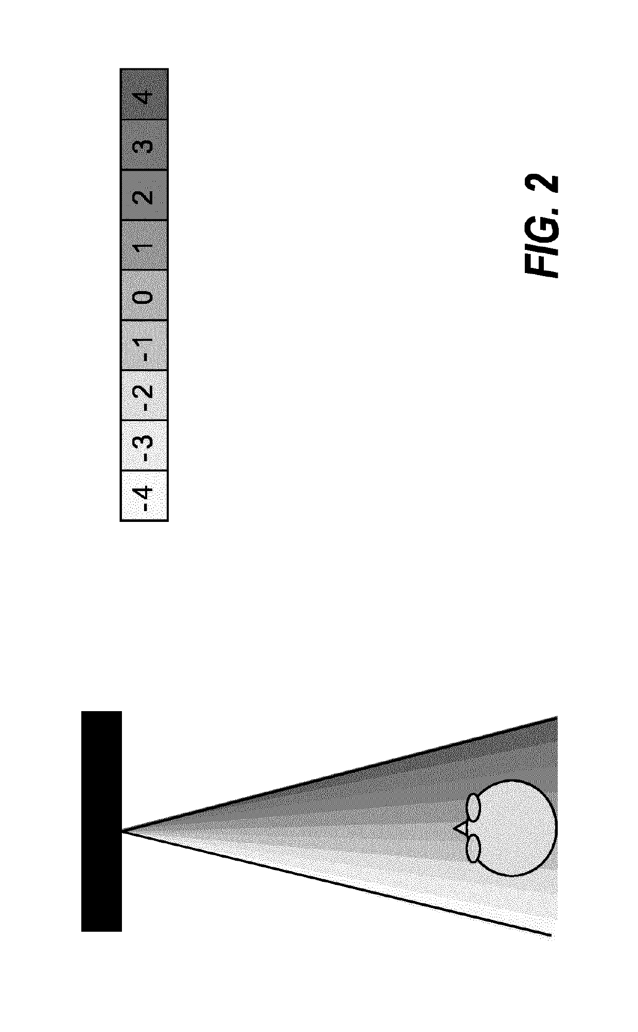
The invention improves depth map creation by reducing the risk of depth reversal, which can cause objects to appear in front of other objects that should be further in the foreground. This approach is especially useful in areas where original depth values may be less accurate or reliable. By using a reliable depth value to determine the depth values in less reliable areas, the invention ensures that perceived depth reversal or disorder is avoided. This results in improved performance and better adaptation to the current conditions.

Problems solved by technology

However, as this may be considered inconvenient to the user, it is in many scenarios preferred to use autostereoscopic displays that use means at the display (such as lenticular lenses, or barriers) to separate views, and to send them in different directions where they individually may reach the user's eyes.
However, in many applications, the provided images may not directly correspond to the desired directions, or more images may be required.
Unfortunately, the depth information generated at sources tend to be suboptimal and in many applications, it is not as accurate as desired.
However, such depth extraction and estimation is problematic and tends to result in non-ideal depth values.
This may again result in artefacts and a degraded three dimensional image quality.
However, such cameras are also associated with imperfections and typically provide suboptimal depth information.
Indeed, for both disparity estimation from a stereo camera setup and an infrared based depth camera, certain areas are inherently hard to estimate.
For example, for disparity estimation occlusion areas exist that are visible in one camera view but not in the other, and this prevents accurate depth determination in such areas.
Also, homogeneous areas that have the same or very similar visual properties in the different input images do not provide suitable basis for disparity estimation.
In such areas, disparity estimates based on matching will be very uncertain.
Also, certain types of objects, such as hair, have a particular infrared scattering behavior that results in a low back-scatter and thus in poor depth estimates from a depth camera.
For both the stereo camera system and a depth sensor there are ways to detect which disparity or depth estimates are reliable and which disparity or depth estimates are not reliable.
However, such an approach may in many scenarios result in suboptimal depth estimates which further may degrade image quality and depth perception for a three dimensional image generated using such depth information.

Method used


Image

  • Processing a depth map for an image
  • Processing a depth map for an image

Examples


Embodiment Construction

[0054]The following description focuses on embodiments of the invention applicable to a depth map for a three dimensional image being a frame of a three dimensional video sequence. However, it will be appreciated that the invention is not limited to this application but may be applied to e.g. individual three dimensional images consisting in an image and an associated depth map. Similarly, the description will focus on an application in a system generating view images for an autostereoscopic display but it will be appreciated that this is merely a specific example, and that the depth processing will be equally applicable to many other applications and uses.

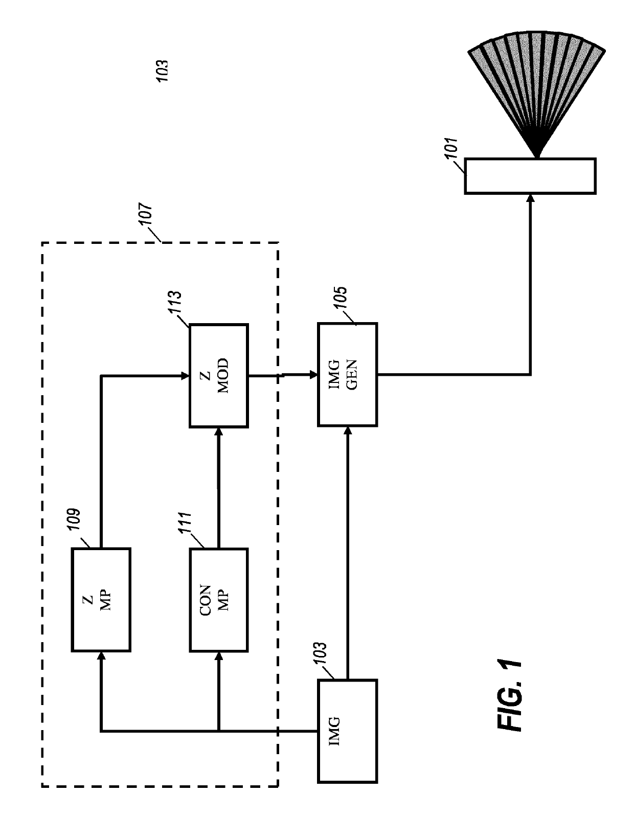
[0055]FIG. 1 illustrates an example of a system in accordance with some embodiments of the invention. In the specific example, images corresponding to different views of an autostereoscopic display 101 are generated from an input three dimensional image. The input three dimensional image may for example be represented by a single ...


PUM


Abstract

An apparatus comprises a depth map source (109) providing a depth map for an image and a confidence map source (111) providing a confidence map with confidence values for pixels of the depth map. The confidence values designate the pixels as confident or non-confident pixels reflecting whether the depth value meets a reliability criterion or not. A depth modifier (113) performs a depth modification operation which modifies depth values for pixels of the depth map. A modified depth value for a first pixel is determined as a current depth value for the first pixel if this is designated as a confident pixel or if there are no confident pixels within a neighborhood set of pixels, and otherwise the modified value is determined as the maximum of the current depth value and a depth value determined as a function of depth values of pixels within the neighborhood set being designated as confident pixels.

Description

CROSS-REFERENCE TO PRIOR APPLICATIONS[0001]This application is the U.S. National Phase application under 35 U.S.C. § 371 of International Application No. PCT / EP2016 / 080164, filed on Dec. 8, 2016, which claims the benefit of EP Patent Application No. EP 5201620.0, filed on Dec. 21, 2015. These applications are hereby incorporated by reference herein.FIELD OF THE INVENTION[0002]The invention relates to a method and apparatus for processing a depth map for an image, and in particular, but not exclusively, to determining a depth map based on estimated disparity values.BACKGROUND OF THE INVENTION[0003]Three dimensional (3D) displays add a third dimension to the viewing experience by providing a viewer's two eyes with different views of the scene being watched. This can be achieved by having the user wear glasses to separate two views that are displayed. However, as this may be considered inconvenient to the user, it is in many scenarios preferred to use autostereoscopic displays that use...

Claims


Application Information

Patent Timeline
Patent Type & Authority Patents(United States)
IPC IPC(8): H04N13/128G06T7/50H04N13/106H04N13/302
CPCH04N13/106G06T7/50H04N13/128H04N13/302G06T2207/10021
Inventor VAREKAMP, CHRISTIAANVANDEWALLE, PATRICK LUC ELS
Owner KONINKLJIJKE PHILIPS NV
Learn More