Steerable catheter with shaft load distributions

a technology of shaft load distribution and catheter, which is applied in the field of minimally invasive instruments and systems, can solve the problems of catheter articulation performance, unrepeatable and inconsistent, and the shaft is compressed and/or experienced other undesired effects, and achieves the effects of reducing outer diameter (od), increasing inner diameter (id), and minimizing lateral stiffness

Active Publication Date: 2019-11-05
AURIS HEALTH INC
View PDF526 Cites 24 Cited by
  • Summary
  • Abstract
  • Description
  • Claims
  • Application Information

AI Technical Summary

Benefits of technology

[0018]Advantageously, various steerable catheter embodiments provided herein use multiple pullwires to steer the distal tip (or “articulating section”) in a single articulation direction. Those pullwires then diverge into a more spaced distribution of pullwires in the proximal shaft section (or “non-articulating section”). This results in a bending moment in the distal articulating section and no bending moment in the shaft of the catheter. This design can be repeated, so that three or more sets of pullwires may be used to create an omnidirectional articulating section. With this design, the articulating section can be independently controlled by pullwires, while the catheter experiences no shaft bending or unintended rotation. In other words, this configuration of pullwires allows a catheter shaft to have minimal lateral stiffness, and yet be able to withstand pullwire forces without experiencing unintended bending or rotation. This configuration also allows for the manufacture of thinner walled catheters, because smaller-diameter pullwires may be used in this design, compared to traditional pullwire systems, resulting in an overall reduction in outer diameter (OD) and / or increase in inner diameter (ID).
[0023]In other embodiments, the system may also include a robotic instrument driver, where the drive mechanism includes a splayer having multiple pulleys, and where each of the pulleys is attached to one group of pullwires. Each of the multiple pulleys interfaces with a motor in the instrument driver to increase tension in the one group of pullwires to articulate the catheter body. Such embodiments may also include a load balancing actuation mechanism for facilitating proportional tensioning of each pullwire within at least one group of pullwires. Examples of load balancing actuation mechanisms include a two-way whiffletree, a three-way whiffletree, an elastic pullwire, a two-way differential, and a three-way differential.

Problems solved by technology

Increasing the lateral flexibility of the catheter, however, introduces catheter navigation problems that may not otherwise occur when the catheter is laterally stiff.
However, the compressive forces from the tensioned pullwire on the relatively flexible catheter shaft also cause the shaft to compress and / or to experience other undesired effects.
The curvature of the catheter shaft may make the articulation performance of the catheter unrepeatable and inconsistent.
In particular, because the pullwires are offset from the neutral axis of the catheter shaft, bending the catheter shaft causes the pullwires on the outside of the curve to tighten while the pullwires on the inside of the curve slacken.
This increased tension on the pullwire 14 on the outside of the bend can cause an unstable position.
Continued attempts to try to find a pullwire to articulate the distal tip against the direction of curvature of the catheter shaft may lead to rotation or windup of the catheter shaft.
This stored energy in the shaft can lead to whipping of the catheter shaft to return to a lower energy state and may injure the patient.
This axial compression may cause undesired lateral deflection in flexible catheter shafts, thereby rendering the catheter mechanically unstable. FIGS. 2A and 2B illustrate how prior art flexible instruments exhibit unwanted lateral shaft deflection when one or more pullwires are pulled.
The shaft of the catheter is being muscled by the pullwires and experiencing unwanted lateral deflection.
The additional lateral deflection of the shaft of the catheter 10 may be undesirable, because it may unintentionally force the catheter against the anatomy.
This has the potential for injury and distracts the operator, because he or she must constantly monitor what the shaft is doing.
This creates an additional problem, because the more space the catheter shaft has to deflect, the greater the impact on the amount of catheter tip articulation.
Undesirable lateral motion related to muscling and undesirable rotational motion related to curve alignment both result from the same forces associated with pullwire tensioning.
Each of these mechanical challenges contributes to the instability and poor control of the catheter tip, as well as decreased catheter tracking performance.
But these changes also laterally stiffen the catheter shaft, making it less maneuverable, and thereby causing new difficulties in tracking the catheter through the vasculature of the patient.
Therefore, the catheter designer is forced to compromise between articulation performance and shaft tracking performance.
While the unirail design locates all pullwires in one location, it is impossible to locate all pullwires exactly on the neutral axis, so the catheter continues to experience some slight unwanted shaft curvature.
Therefore, the shaft of the unirail catheter cannot be designed with very low lateral stiffness.
However, continuously spiraling the pullwires leads to increased friction in the catheter system, and so there is still a tradeoff between shaft flexibility and articulation performance.
However, the use of coil pipes adds to the cost of the catheter and takes up more space in the shaft, resulting in a thicker catheter wall.
Such a design is not appropriate for catheters with small outer diameters intended for use in narrow vasculature.
One barrier to achieving a small OD:ID ratio is the diameter of the pullwires.
Accordingly, each design has significant tradeoffs.
Thus, although a number of innovations have been made, major unresolved challenges remain when using pullwires to articulate the distal tip of a flexible catheter.

Method used


Image

  • Steerable catheter with shaft load distributions
  • Steerable catheter with shaft load distributions
  • Steerable catheter with shaft load distributions

Examples


Embodiment Construction

[0073]Referring now to the drawings, illustrative embodiments are shown in detail. Although the drawings represent the embodiments, the drawings are not necessarily to scale, and certain features may be exaggerated to better illustrate and explain an innovative aspect of an embodiment. Further, the embodiments described herein are not intended to be exhaustive or otherwise limit or restrict the invention to the precise form and configuration shown in the drawings and disclosed in the following detailed description.

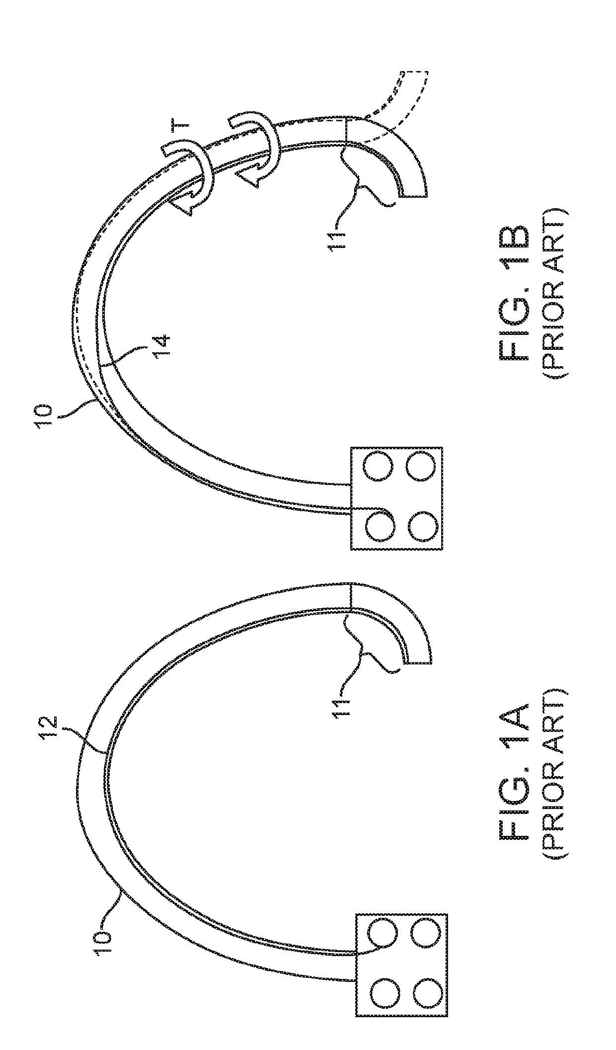
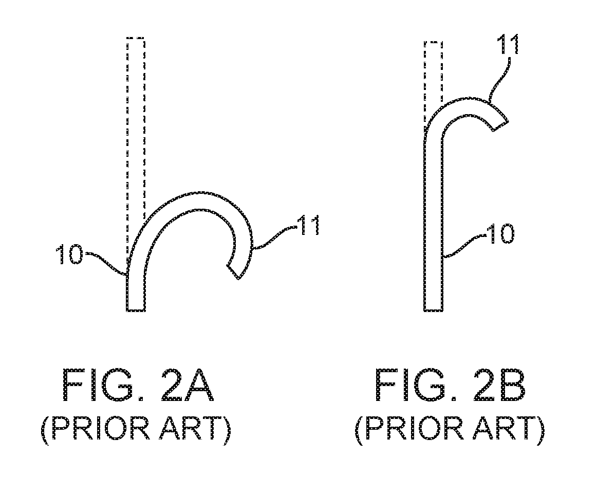
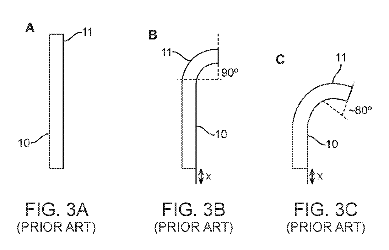
[0074]To address at least some of the challenges with steerable catheters discussed above, a number of embodiments of a “polyrail” catheter will be described in detail below. In general, these embodiments include multiple pullwires (also referred to as “control wires,” or simply, “wires”), which are spaced around a circumference of a catheter along a proximal portion of the catheter shaft and then converge toward one another so that they are touching or immediately adjacen...


PUM


Abstract

A steerable catheter system may include a flexible elongate catheter body, a drive mechanism at the proximal end of the catheter body, and at least one group of pullwires extending along a length of the catheter body. The catheter body may include a distal articulating section and a proximal non-articulating section. Each group of pullwires includes at least two pullwires, and each of the pullwires is anchored at a first end to the distal end of the catheter body and at a second end to the drive mechanism. The pullwires of each group are positioned close to one another in the catheter wall to concentrate the forces and cause deflection along the articulating section of the catheter body and diverge away from one another to reach a more separated distribution around a circumference of the catheter body to distribute the forces and prevent deflection along the non-articulating section.

Description

FIELD[0001]The invention relates generally to minimally-invasive instruments and systems, such as manually or robotically steerable catheter systems. More specifically, the invention relates to steerable catheter systems for performing minimally invasive diagnostic and therapeutic procedures.BACKGROUND[0002]Robotic steerable catheter systems typically include a flexible catheter shaft having an articulation section at a distal tip. These systems are designed to facilitate access to distal target sites in the human anatomy and require simultaneous articulation of the distal tip with continued insertion or retraction of the catheter. Pullwire based articulating catheters typically have pullwires passing through the shaft, and each pullwire is anchored to a fixed location around the distal tip. Each pullwire is then selectively tensioned to articulate the tip in various directions. As such, the catheter shaft should be laterally flexible to follow the curvature in the anatomy, but axia...

Claims


Application Information

Patent Timeline
Patent Type & Authority Patents(United States)
IPC IPC(8): A61B34/00A61B34/30A61M25/01A61B34/37
CPCA61B34/30A61B34/71A61M25/0147A61B2034/301A61B2034/715A61M2025/015A61B34/37
Inventor JOSEPH, MILESMACNAMARA, FRANCIS
Owner AURIS HEALTH INC
Why Eureka
Try Eureka