Stemless shoulder implant with fixation components

a stemless, shoulder technology, applied in the direction of shoulder joints, prostheses, medical science, etc., can solve the problems of difficult removal of humeral components, disadvantageous removal of stems, and difficulty in removing humeral components, so as to improve the security of stemless humeral anchors

Active Publication Date: 2019-11-05
HOWMEDICA OSTEONICS CORP
View PDF270 Cites 18 Cited by
  • Summary
  • Abstract
  • Description
  • Claims
  • Application Information

AI Technical Summary

Benefits of technology

[0008]Accordingly, there is a need for a stemless humeral component or prosthesis designed to preserve bone in initial implantation while enhancing initial pull-out resistance. Preferably enhanced initial dislodgement resistance will also provide excellent long term fixation. Furthermore, there is a need for new systems, kits and methods that minimize risk of dislodgement in a number of situations, including during revision, e.g., from an anatomical configuration to a reverse configuration or from a reverse to an anatomical configuration
[0010]In another embodiment, a humeral anchor kit is provided that includes a humeral anchor and at least one screw. The humeral anchor is configured to form a part of or support a part of a shoulder prosthesis. The humeral anchor has a distal portion configured to be anchored in a proximal region of a humerus and a proximal portion. The proximal portion includes a proximal face configured to engage an articular component within a periphery thereof. The proximal portion also includes at least one aperture disposed adjacent to the periphery. The aperture is configured to receive a screw advanced therethrough into bone disposed around or distal to the humeral anchor when implanted. The engagement of the humeral anchor having received the screw is enhanced.
[0012]In another embodiment, a surgical method is provided. In the method, a prosthetic shoulder joint comprising an anatomical configuration or a reverse configuration is exposed. A first articular component is removed. The first articular component has a convex surface corresponding to an anatomic configuration or a concave surface corresponding to a reverse configuration. A stemless humeral anchor is exposed by removing the articular component. A first screw is advanced through a first aperture of a plurality of peripheral apertures disposed about the stemless humeral anchor. The first screw is advanced into bone of the humerus. A second screw is advanced through a second aperture of the stemless humeral anchor and into cancellous bone of the humerus to enhance security of the stemless humeral anchor in the humerus. A second articular component is coupled to the stemless humeral anchor after the first screw and the second screw are advanced into the bone through the stemless humeral anchor.

Problems solved by technology

In certain cases, insertion of the stem disadvantageously requires bone to be removed to fit the stem to the canal due to patient-to-patient anatomical variation.
Another disadvantage of this approach is that integration of the stem into the bone through a natural process of bone ingrowth can make it difficult to remove the humeral component if it becomes necessary to replace the humeral component with another device.
Due to the length of the stem it can be required to remove a lot of bone to facilitate removal of the stem; this complicates the ability to anchor a revision stem into the remaining bone.
Stemless humeral component designs can be more challenging to secure to the humerus.
While such designs perform well over time, there is a risk in the early days and weeks after surgery where such ingrowth has not yet occurred that the stemless humeral component will be dislodged from the humerus.
Dislodgement may also occur due to excessive wear, forces applied thereto during a revision surgery or other high load conditions.

Method used


Image

  • Stemless shoulder implant with fixation components
  • Stemless shoulder implant with fixation components
  • Stemless shoulder implant with fixation components

Examples


Embodiment Construction

[0034]While the present description sets forth specific details of various embodiments, it will be appreciated that the description is illustrative only and should not be construed in any way as limiting. Furthermore, various applications of such embodiments and modifications thereto, which may occur to those who are skilled in the art, are also encompassed by the general concepts described herein. Each and every feature described herein, and each and every combination of two or more of such features, is included within the scope of the present invention provided that the features included in such a combination are not mutually inconsistent.

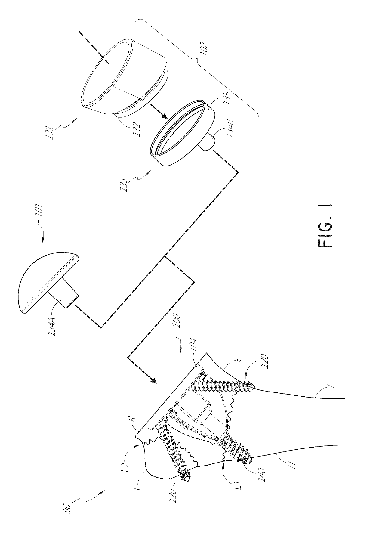
[0035]FIG. 1 shows a humeral assembly 96 that includes a humeral anchor assembly 100 having a humeral anchor 104. The humeral anchor 104 can be a stemless humeral anchor, as discussed further below. FIG. 1 shows two versions of the humeral assembly 96. In the first version of the humeral assembly 96, an articular component 101 of an anatomic pros...


PUM


Abstract

A humeral anchor assembly is provided that includes a humeral anchor and at least one screw. The humeral anchor is configured to form a part of or support a part of a shoulder prosthesis. The humeral anchor has a distal portion configured to be anchored in a proximal region of a humerus and a proximal portion. The proximal portion includes a proximal face configured to engage an articular component within a periphery thereof. The proximal portion also includes at least one aperture disposed adjacent to the periphery. The at least one screw is disposed through the at least one aperture. The screw has a first end portion engaged with the proximal portion of the anchor and a second end portion disposed in or through cortical bone of the humerus.

Description

INCORPORATION BY REFERENCE TO ANY PRIORITY APPLICATIONS[0001]Any and all applications for which a foreign or domestic priority claim is identified in the Application Data Sheet as filed with the present application are hereby incorporated by reference under 37 C.F.R. § 1.57.BACKGROUND OF THE INVENTION[0002]Field of the Invention[0003]The present disclosure relates to a stemless humeral component of a shoulder joint prosthesis.[0004]Description of the Related Art[0005]In a shoulder joint, the head of the humerus interacts with the glenoid cavity of the scapula in a manner similar to a “ball and socket” joint. Over time, it may become necessary to replace the shoulder joint with a prosthetic shoulder joint including a humeral component.[0006]Traditionally, the humeral component includes a humeral head and a stem. The stem is configured to be inserted into an intramedullary canal of the humerus. In certain cases, insertion of the stem disadvantageously requires bone to be removed to fi...

Claims


Application Information

Patent Timeline
Patent Type & Authority Patents(United States)
IPC IPC(8): A61F2/40A61B17/86A61B17/04A61F2/30
CPCA61F2/4003A61B17/86A61F2/4014A61F2002/30874A61F2220/0016A61F2002/30289A61B17/0401A61F2250/006A61F2002/3069A61F2002/30884A61B2017/0414A61F2002/30886A61F2002/30794A61F2002/4007A61F2002/4051A61F2002/30784A61B2017/044A61F2002/30873A61F2002/3079
Inventor EMERICK, BRADLEY GRANTSTRZELECKI, BRIAN M.
Owner HOWMEDICA OSTEONICS CORP
Why Eureka
Try Eureka