LED fluorescent lamp emulator circuitry

a fluorescent lamp and circuit board technology, applied in the field of lighting, can solve the problems of low efficiency, low efficiency, and simple non-isolation of magnetic ballasts, and achieve the effect of lowering the ionization voltage and high impedan

Active Publication Date: 2019-11-05
ELB ELECTRONICS
View PDF28 Cites 1 Cited by
  • Summary
  • Abstract
  • Description
  • Claims
  • Application Information

AI Technical Summary

Benefits of technology

[0015]A fluorescent lamp has high impedance before it ionizes. Only glow current less than 1 ma flows thru the lamp when the ballast starts and the open circuit voltage is less than the ionization voltage. Filament voltage lowers the ionization voltage across the lamp. The purpose of this invention is to emulate operation of a fluorescent lamp with LED replacement lamp that will operate normally on both magnetic and electronic ballast and prevent failure of the UL935 thru lamp leakage test.

Problems solved by technology

One of the major challenges has been the fact that many of those environments include large numbers of lighting fixtures which already include ballasts (magnetic and / or electronic) that are specifically designed for powering discharge lamps.
Magnetic ballasts, however, are simple non-isolated autotransformers that have voltage potential relative to safety ground.
When replacing lamp with the ballast energized there is a potential shock hazard between the bipins of the lamp and the safety grounded fixture.
However, magnetic ballast output leads are not DC isolated from the mains voltage and safety ground.
Any resulting voltage which may exist in a magnetic ballast is insufficient to ionize the gas and cause conduction above the test limits for a conventional discharge lamp.
However, LED lamps have much lower conduction voltage than a traditional fluorescent lamp and conduction can occur, and the UL935 test failed, for voltages exceeding the conduction voltage of the LED lamp.

Method used


Image

  • LED fluorescent lamp emulator circuitry
  • LED fluorescent lamp emulator circuitry
  • LED fluorescent lamp emulator circuitry

Examples


Embodiment Construction

[0025]In the following description of the preferred embodiments, reference is made to the accompanying drawings which show by way of illustration specific embodiments in which the invention may be practiced. Wherever possible, the same reference numbers will be used throughout the drawings to refer to the same or like parts. It is to be understood that other embodiments may be utilized and structural and functional changes may be made without departing from the scope of the present invention.

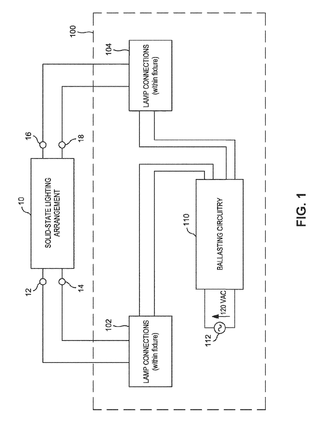
[0026]FIG. 1 depicts a solid-state lighting arrangement 10 that is intended as a drop-in discharge lamp replacement for use within an existing lighting fixture 100.

[0027]As described in FIG. 1, lighting fixture 100 includes lamp connections 102, 104 (between which one or more lamps are usually connected) and ballasting circuitry 110 (which typically receives a conventional source 112 of AC power, such as 120 volts rms at 60 hertz).

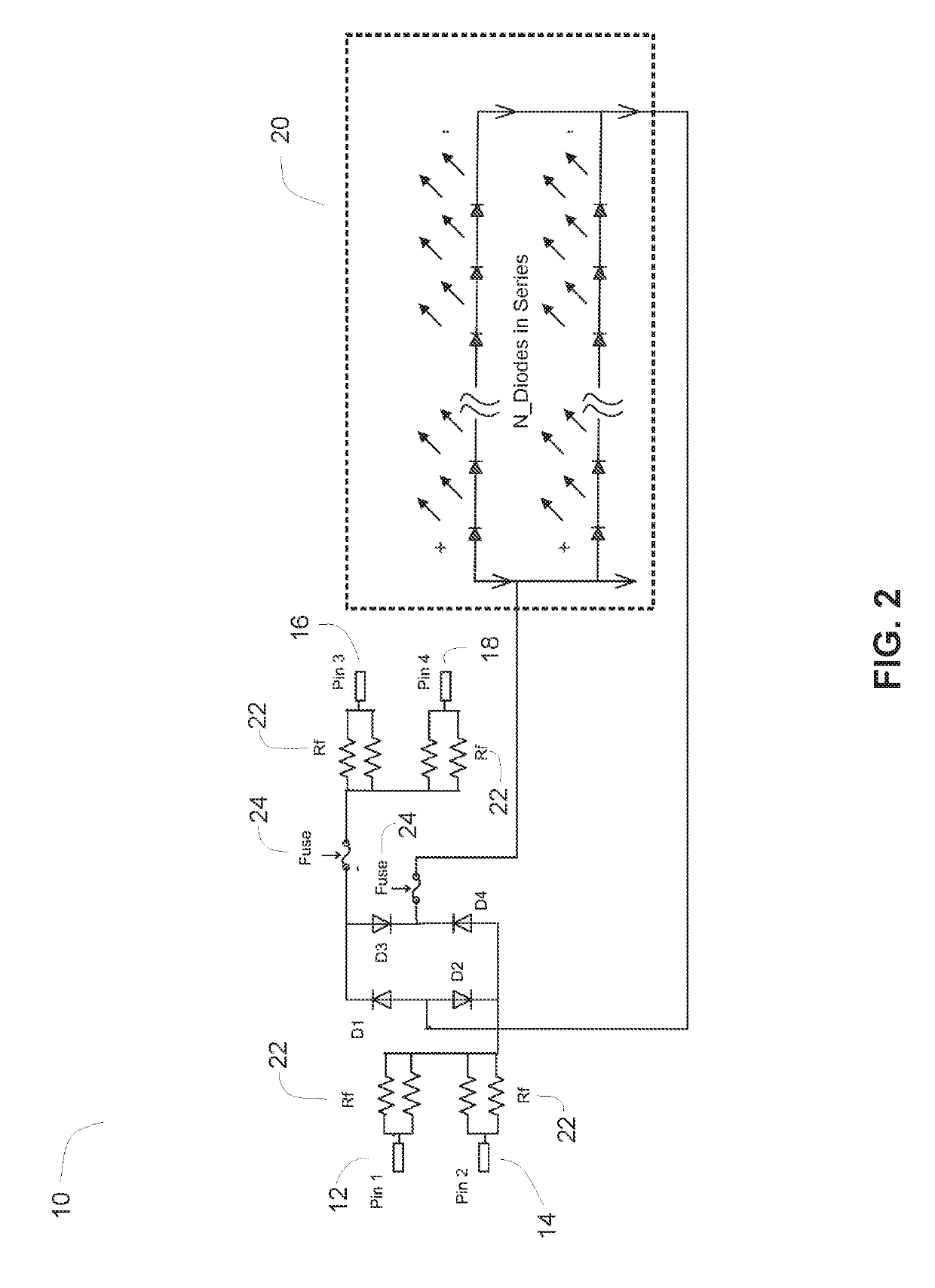
[0028]During operation, ballasting circuitry 110 provides a suita...


PUM


Abstract

Circuitry 31 for a solid-state lighting arrangement 20 designed for as a replacement for a gas discharge lamp used in a lighting fixture having a ballast. The circuitry 31 unsafe flow of current through the solid-state lighting arrangement 20, under non-operational conditions and during installation of the lighting arrangement, so as to provide compatibility with safety standards for use with discharge lamps.

Description

RELATED APPLICATION[0001]This is a continuation of U.S. patent application Ser. No. 16 / 029,522, filed Jul. 6, 2018, the disclosures of which are incorporated herein by reference.FIELD OF INVENTION[0002]The present invention relates to lighting in commercial and residential environments, and more particularly to a solid-state lighting arrangement that is a drop-in replacement for conventional ballasted gas discharge lamps. This invention more particularly relates to a solid-state lighting arrangement that includes a circuitry to allow for safe operation and compliance with existing safety standards originally drafted for conventional ballasted gas discharge lamps, e.g. fluorescent lamps.BACKGROUND OF THE INVENTION[0003]Due to advances in semiconductors and related technologies, light-emitting diodes (LEDs) have become so cost-effective as to make them feasible for lighting systems that previously relied upon incandescent or discharge lamps. Consequently, a substantial variety of LED-...

Claims


Application Information

Patent Timeline
Patent Type & Authority Patents(United States)
IPC IPC(8): H05B33/08H05B44/00
CPCH05B33/089H05B45/36H05B45/3578H05B45/382H05B47/26
Inventor CHENG, XIAOXIANG
Owner ELB ELECTRONICS
Why Eureka
Try Eureka