Energy harvesting for wireless sensor operation and data transmission

a wireless sensor and energy harvesting technology, applied in the field of collecting and transmitting data, can solve the problems of wireless sensors that still require system power in order to operate, unobtrusive devices scavenge, and mems systems only demonstrated 8 microwatts of power, etc., to achieve efficient energy transfer, high capacity storage device, and high impedance

Active Publication Date: 2005-06-02
LORD CORP
View PDF29 Cites 74 Cited by
  • Summary
  • Abstract
  • Description
  • Claims
  • Application Information

AI Technical Summary

Benefits of technology

[0025] It is an advantage of the present invention that the data collection device can provide information about the environment using energy harvested from the environment; and
[0026] It is a further advantage of the present invention that the data collection device does not itself require maintenance for replacing or recharging batteries.
[0027] These and other objects, features, and advantages of the invention are accomplished by a device for powering a load from an ambient source of energy. The device comprises an energy harvesting device for harvesting energy from the ambient source of energy wherein the rate energy is harvested from the ambient source of energy is below that required for directly powering the load. A storage device is connected to the energy harvesting device. The storage device receives electrical energy from the energy harvesting device and is for storing the electrical energy. A controller is connected to the storage device is for monitoring the amount of electrical energy stored in the storage device and for switchably connecting the storage device to the load when the stored energy exceeds a first threshold.
[0028] Another aspect of the invention is an energy harvesting system comprising a piezoelectric transducer and a rectifier. The system also includes a reactive device having a high impedance approximately matching impedance of the piezoelectric transducer at its operating frequency for efficiently transferring energy from the piezoelectric transducer to the reactive device. The system also includes a low impedance high capacity storage device. The system also includes a circuit for monitoring voltage across the reactive device, and for transferring the charge from the reactive device to the low impedance high capacity storage device when the voltage across the reactive device reaches a specified voltage value.
[0029] Another aspect of the invention is a device for sensing temperature or pressure in a tire. The device includes a tire and a PZT mounted on the tire. The device also includes a circuit for harvesting energy from the PZT, wherein the circuit comprises an element having an impedance approximately matching impedance of the PZT. The device also includes a sensing module connected to the circuit, the sensing module including a sensor and a circuit for wirelessly transmitting sensor information.

Problems solved by technology

The unobtrusive devices scavenge electricity from the forces exerted on a shoe during walking.
However, these MEMs systems only demonstrated 8 microwatts of power.
However, wireless sensors still require system power in order to operate.
If power outages occur, critical data collected by the sensors may be lost.
In other cases however, the need to hard wire to a power system defeats the advantages of wireless sensors, and this may be unacceptable for many applications.
Traditional batteries, however, become depleted and must be periodically replaced or recharged, adding an additional maintenance task that must be performed.
This is particularly a problem for monitors used for a condition based maintenance program since it adds additional maintenance for the condition based monitoring system itself.
None of the systems for sensing changes in the environment have collected available mechanical energy to provide the electricity for running the sensors, storing data from the sensor, or communicating the data externally.

Method used


Image

  • Energy harvesting for wireless sensor operation and data transmission
  • Energy harvesting for wireless sensor operation and data transmission
  • Energy harvesting for wireless sensor operation and data transmission

Examples


Embodiment Construction

[0049] The present inventors recognized that substantial efficiency in collecting, storing, and transmitting data from wireless sensors could be provided by harvesting energy from the environment.

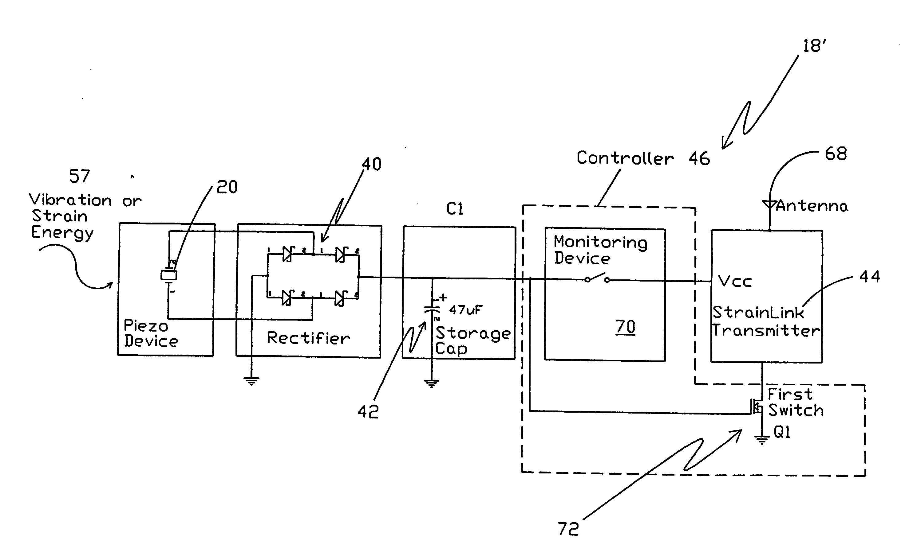
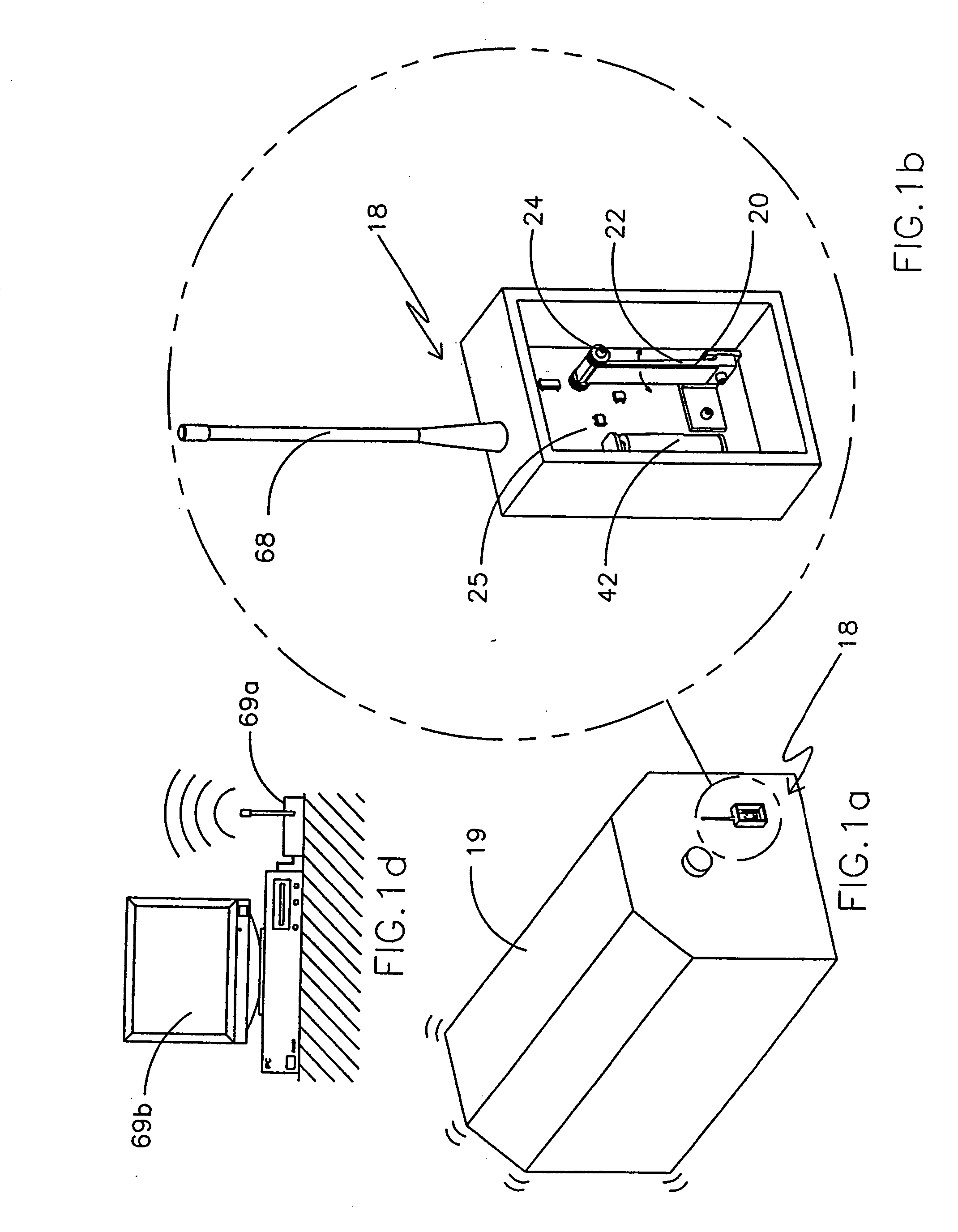
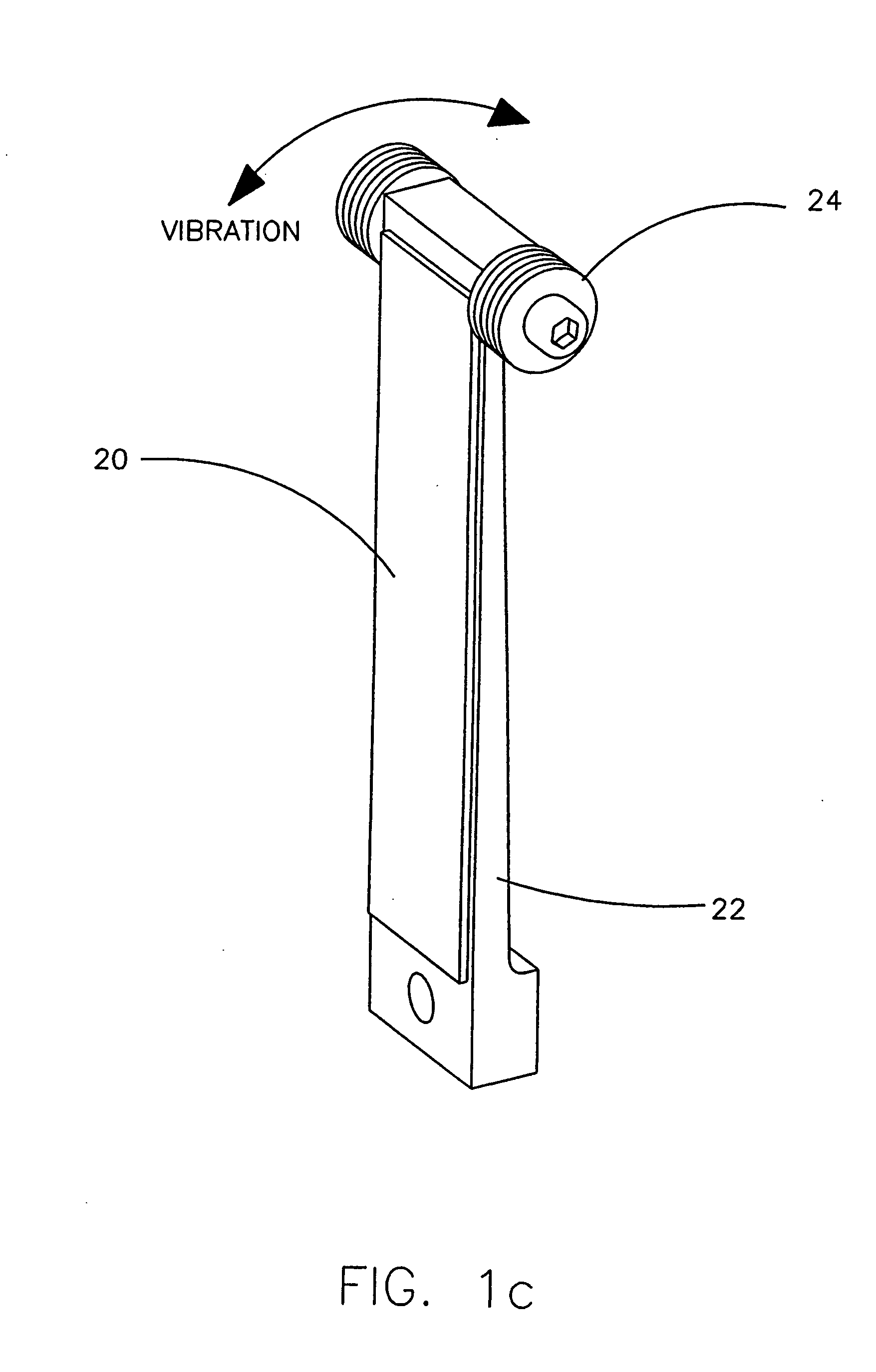
[0050] This invention is aimed at developing a new class of sensing systems that can wirelessly report data without the need for maintaining or replacing batteries. Instead, the sensing systems rely on harvesting vibration, strain energy, or magnetic coupled energy from the local environment for conversion to electrical power for storage and use to collect, store, or transmit data by the sensing system. Thus, machines, structures, and live subjects can be monitored without the need for replacing or recharging batteries or for a battery maintenance schedule. Truly smart structures and machines will thus be able to autonomously report their condition throughout their operating life without the mechanism used for reporting the data itself requiring maintenance. The system can be used to run a...


PUM


Abstract

A device for powering a load from an ambient source of energy is provided. The device includes an energy harvesting device for harvesting energy from the ambient source of energy wherein the rate energy is harvested from the ambient source of energy is below that required for directly powering the load. A storage device is connected to the energy harvesting device. The storage device receives electrical energy from the energy harvesting device and is for storing the electrical energy. A controller is connected to the storage device for monitoring the amount of electrical energy stored in the storage device and for switchably connecting the storage device to the load when the stored energy exceeds a first threshold. The system can be used for powering a sensor and for transmitting sensor data, such as tire pressure.

Description

RELATED APPLICATIONS [0001] This patent application is a divisional of U.S. patent application Ser. No. 10 / 379,223, incorporated herein by reference, and claims benefit of provisional patent application 60 / 362,432, filed Mar. 7, 2002, incorporated herein by reference and provisional patent application 60 / 443,120, filed Jan. 28, 2003, incorporated herein by reference. This patent application is related to the following US patent applications: [0002] U.S. Ser. No. 09 / 731,066, docket number 1024-034, filed Dec. 6, 2000, incorporated herein by reference; [0003] U.S. Ser. No. 09 / 757,909, docket number 1024-035, filed Jan. 10, 2001, incorporated herein by reference; [0004] U.S. Ser. No. 09 / 801,230, docket number 1024-036, filed Mar. 7, 2001, incorporated herein by reference; [0005] U.S. Ser. No. 09 / 768,858, docket number 1024-037, filed Jan. 24, 2001, incorporated herein by reference; [0006] U.S. Ser. No. 09 / 114,106, docket number 1024-041, filed Jul. 11, 1998, incorporated herein by refe...

Claims


Application Information

Patent Timeline
Patent Type & Authority Applications(United States)
IPC IPC(8): G06F11/00H01L41/113H02H3/24H02J1/10H02J1/12H02J7/32H02J7/34
CPCB60C23/0411H01L41/1136H02N2/186H02J7/345H02J7/32H10N30/306
Inventor HAMEL, MICHAEL JOHNARMS, STEVEN W.TOWNSEND, CHRISTOPHER P.CHURCHILL, DAVID L.
Owner LORD CORP
Why Eureka
Try Eureka