Rf surge protection device

a surge protection device and radio frequency technology, applied in the direction of overvoltage protection resistors, emergency protection arrangements for limiting excess voltage/current, disturbance protection, etc., can solve the problem of difficulty in matching the impedance of the surge protection device with the system, severe damage and/or destruction of electronic equipment,

Inactive Publication Date: 2004-08-31
INFINITE ELECTRONICS INT INC
View PDF39 Cites 81 Cited by
  • Summary
  • Abstract
  • Description
  • Claims
  • Application Information

AI Technical Summary

Benefits of technology

One embodiment of the present invention is a surge protection device, which includes an input path for receiving an rf signal, dc power, and a surge, an output path for propagating the rf signal, and a dc blocking device coupled in series between the input path and the output path. The surge protection device also includes a first inductor coupled to the input path for isolating the rf signal and providing a path for the dc power and the surge, a gas tube coupled to the first inductor for routing a portion of the surge to a ground plane, a second inductor coupled to the first inductor for providing a path for the dc power, and a metal oxide varistor coupled to the second inductor for routing a portion of the surge to the ground plane. Furthermore, the surge protection device includes a third inductor coupled to the second inductor for providing a path for the dc power, a diode coupled to the third inductor for routing a portion of the surge to the ground plane, and a fourth inductor coupled to the third inductor for providing a path for the dc power to the output path. The diode conducts prior to the MOV, which conducts prior to the gas tube. Therefore, the diode diverts a first portion of the surge, the MOV diverts a second portion of the surge, and the gas tube diverts a third portion of the surge to the common ground. In one embodiment, the diode responds in nanoseconds, the MOV a short time thereafter, and the gas tube is the last element to respond to the surge. This sequence prevents most of the surge from reaching the output path.
Advantages of the surge protection device include dc circuitry on a plate or circuit board for passing dc currents, isolation from the rf signal path with inductors calculated to be high impedance to the respective rf bandwidth, and a unique cavity, which provides for an improved rf signal path and better impedance matching of the surge protection device and the system as compared to the more conventional rectangular cavity.

Problems solved by technology

Large variations in the power and transmission line currents and voltages can change the operating frequency range of the electronic equipment and can severely damage and / or destroy the electronic equipment.
For example, lightning is a complex electromagnetic energy source having potentials estimated at from 5 million to 20 million volts and currents reaching thousands of amperes that can severely damage and / or destroy the electronic equipment.
One drawback of conventional surge protection devices is the difficulty in impedance matching the surge protection device with the system.
Another drawback of conventional surge protection devices is the elevated voltage at which they become conductive and the higher throughput energy levels.

Method used


Image

  • Rf surge protection device
  • Rf surge protection device
  • Rf surge protection device

Examples


Embodiment Construction

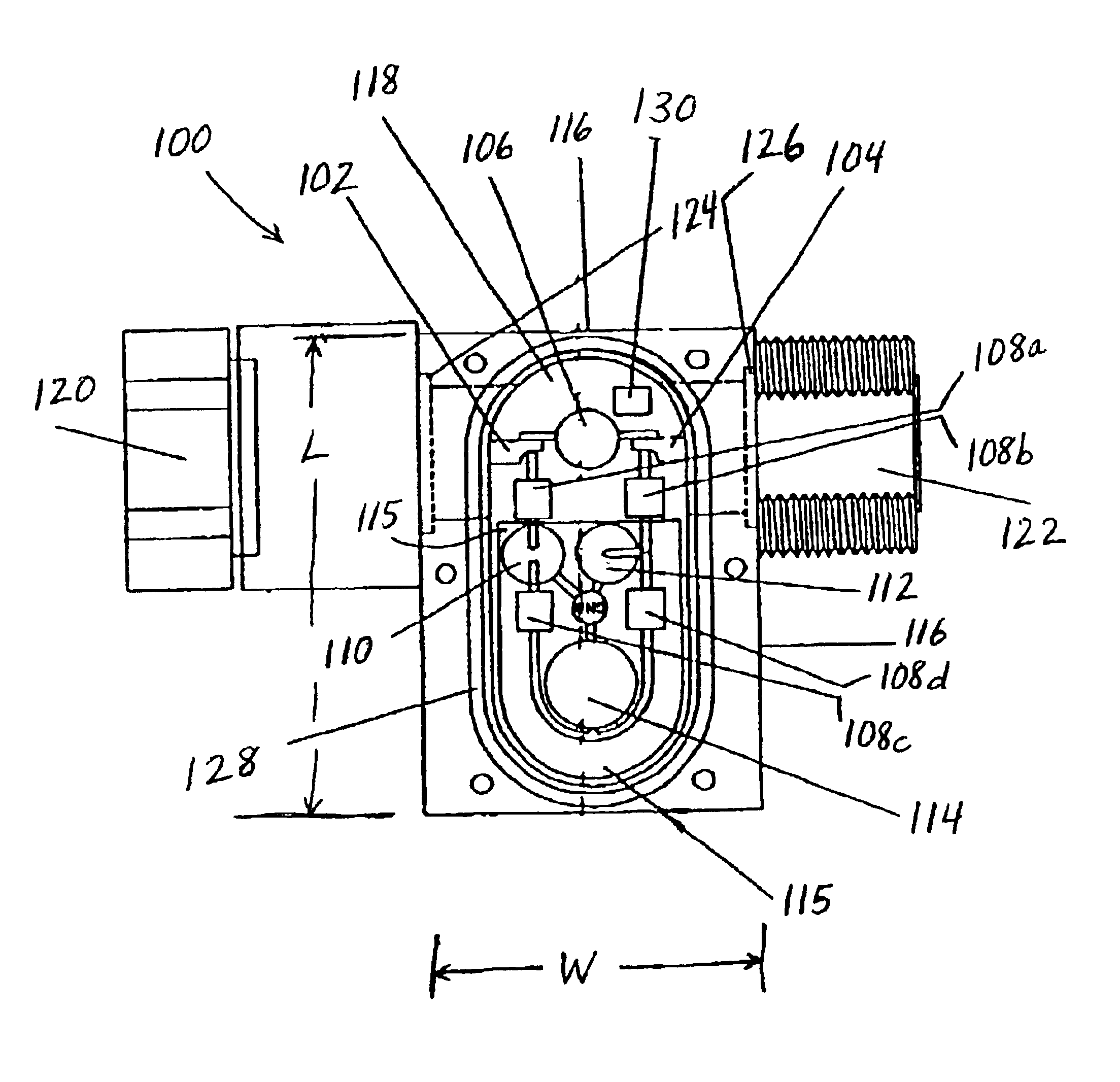
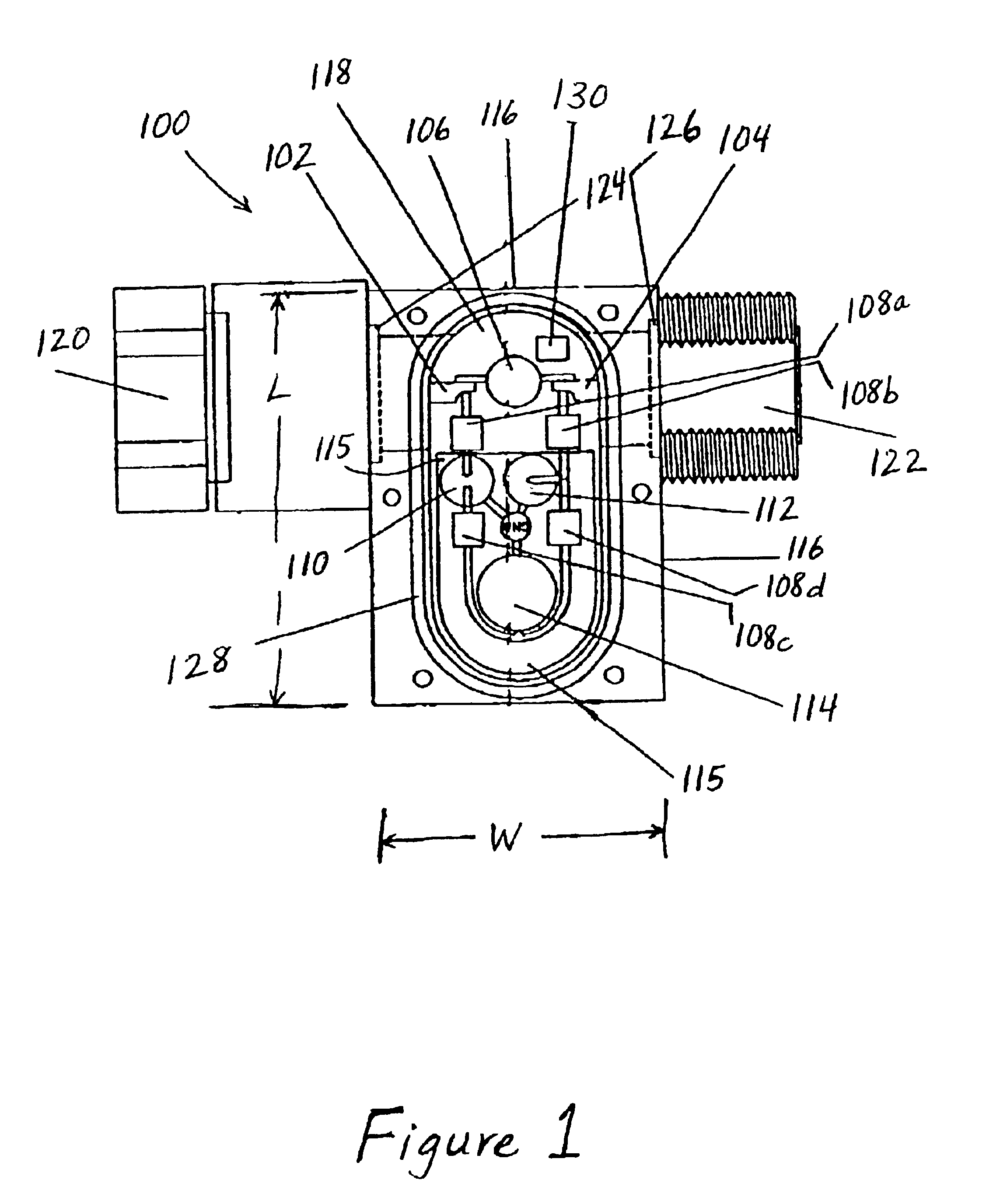
Surge protection devices that implement the various features of the present invention will now be described with reference to the drawings. The drawings and the associated descriptions are provided to illustrate embodiments of the present invention and not to limit the scope of the present invention. Reference in the specification to "one embodiment" or "an embodiment" is intended to indicate that a particular feature, structure, or characteristic described in connection with the embodiment is included in at least an embodiment of the invention. The appearances of the phrase "in one embodiment" in various places in the specification are not necessarily all referring to the same embodiment. Throughout the drawings, reference numbers are re-used to indicate correspondence between referenced elements. In addition, the first digit of each reference number indicates the figure in which the element first appears.

Referring now more particularly to the drawings, FIG. 1 is a top plan view of...


PUM


Abstract

A surge protection device is disclosed that includes an input path for receiving an rf signal, dc power, and a surge, an output path for propagating the rf signal, and a dc blocking device coupled in series between the input path and the output path. The surge protection device also includes a first inductor coupled to the input path for isolating the rf signal and providing a path for the dc power, a gas tube coupled to the first inductor for routing a portion of the surge to a ground plane, a second inductor coupled to the first inductor for providing a path for the dc power, and a metal oxide varistor coupled to the second inductor for routing a portion of the surge to the ground plane. Furthermore, the surge protection device includes a third inductor coupled to the second inductor for providing a path for the dc power, a diode coupled to the third inductor for routing a portion of the surge to the ground plane, and a fourth inductor coupled to the third inductor for providing a path for the dc power to the output path.

Description

BACKGROUND OF THE INVENTION1. Field of the InventionThe present invention relates generally to the field of surge protection, and more particularly to a radio frequency (rf) surge protection device.2. Description of the Related ArtSurge protection devices protect electronic equipment from being damaged by large variations in the current and voltage across power and transmission lines resulting from lightning strikes, switching surges, transients, noise, incorrect connections, and other abnormal conditions or malfunctions. Large variations in the power and transmission line currents and voltages can change the operating frequency range of the electronic equipment and can severely damage and / or destroy the electronic equipment. For example, lightning is a complex electromagnetic energy source having potentials estimated at from 5 million to 20 million volts and currents reaching thousands of amperes that can severely damage and / or destroy the electronic equipment.Surge protection devi...

Claims


Application Information

Patent Timeline
Patent Type & Authority Patents(United States)
IPC IPC(8): H01Q1/50H01Q1/00
CPCH01Q1/002H01Q1/50
Inventor BARTEL, KARL C.PELTIER, ARTHUR
Owner INFINITE ELECTRONICS INT INC
Why Eureka
Try Eureka