Filing apparatus for a rotary press

a filling apparatus and rotary press technology, which is applied in the field of filling apparatus for filling cavities in rotary presses, can solve the problems of not offering satisfactory loosening of pressing materials, affecting the flowability, and difficult to find a stirrer blade configuration that realizes all of the various goals, and achieves high press outputs.

Active Publication Date: 2019-11-12
FETTE COMPACTING GMBH
View PDF16 Cites 0 Cited by
  • Summary
  • Abstract
  • Description
  • Claims
  • Application Information

AI Technical Summary

Benefits of technology

[0005]The effect of the stirrer blades of the stirrer blade wheels on the cavity filling quality is dependent inter alia on the pressing material to be pressed. The stirrer blades can have a significant influence on the transported amount of pressing material, and / or on the extent to which bridge formation is prevented, and / or loosening. In addition, by selecting appropriate stirrer blades, disadvantageous effects can be prevented such as a decomposition or heating of the pressing material. It is, however, difficult to find a stirrer blade configuration that realizes all of the various goals. For example, a certain stirrer blade configuration can ensure an effective transportation of the pressing material to the cavities. However, it does not offer satisfactory loosening of the pressing material at all times. Conversely, a stirrer blade configuration that, for example, ensures effective loosening of the pressing material may not ensure satisfactory transportation of the pressing material to the cavities. A conflict between goals accordingly exists in practice.
[0006]Based on the presented prior art, the object of the invention is therefore to provide a filling apparatus of the aforementioned type which also satisfactorily meets various requirements with regard to cavity filling.BRIEF SUMMARY OF THE INVENTION
[0007]For a filling apparatus of the aforementioned type, the invention achieves the object in that a first rotatably driven stirrer blade wheel with stirrer blades and a second rotatably driven stirrer blade wheel with stirrer blades are arranged in the filling chamber, wherein the first and second rotatably driven stirrer blade wheel differ in terms of their geometry, and / or their direction of rotation, and / or their rotary speed.
[0008]The filling apparatus according to the invention is provided for use in a rotary press, in particular a rotary tablet press. The rotary press can also be a multiple rotary press, in particular, a double rotary press. A plurality of, in particular two filling apparatuses, pressing stations, ejector stations, or other suitable components are then provided. This is known per se. The rotor of such a rotary press possesses a rotary drive that rotatably drives the rotor, in particular the die plate with the upper and lower punches, for example by means of a drive shaft at the rotor rotary speed. The die plate can be designed as a single piece or be constructed from individual die segments. The cavities can be formed by holes introduced directly in the die plate, or by releasable dies inserted in seats in the die plate. In the filling apparatus, the cavities of the die plate are filled with a filling material such as a powder. Then the filling material is pressed within the cavities in a known manner by the top and bottom punch of the rotary press in the cavities into a pellet, especially a tablet. After the pellets are expelled from the cavities, for example by the bottom punch of the rotary press, the pellet is ejected from the rotary press in an ejector station. The ejector station can, for example, comprise a scraper arranged directly above the die plate which scrapes off the ejected pellets from the die plate passing below the scraper toward a discharge channel.
[0009]The filling apparatus comprises a filling material reservoir that, for example, can be connected by a feed section to the filling chamber. The filling material passes from the filling material reservoir, for example via the feed section, into the filling chamber, in particular under the force of gravity. The filling material reservoir can be designed in the shape of a funnel. When the rotary press is in an installed state, the filling chamber is located directly above the die plate so that, during operation, filling material from the filling chamber can fall through the filling opening, in particular under the force of gravity, into the cavities of the die plate rotating below the filling chamber. In an embodiment, the filling chamber can be a filling shoe.
[0010]According to the invention, at least two rotationally driven stirrer blade wheels are arranged in the filling chamber of the filling apparatus. The stirrer blade wheels each possess stirrer blades. The filling apparatus possesses one or more rotary drives that rotatably drive the stirrer blade wheel or respectively, wheels. The stirrer blades of the stirrer blade wheels are arranged around the perimeter of the stirrer blades wheels and rotate in the filling chamber filled with the filling material. The first and second stirrer blades differ in terms of their geometry, and / or their direction of rotation, and / or rotary speed. In particular, the geometry of the stirrer blades of the first and second stirrer blades wheel can differ. In an embodiment, the stirrer blades can possess different cross-sections. In another embodiment, the stirrer blades of one stirrer blade wheel can be thicker than the stirrer blades of the other stirrer blade wheel. The direction of rotation, or respectively the rotary speed and in particular the geometry of the stirrer blades influence the availability and flowability of the filling material to different degrees. The selection of the stirrer blade configuration to be used depends on the nature of the filling material to be pressed. By providing, according to the invention, at least two stirrer blade wheels of a different configuration in a filling chamber, the advantages of different stirrer blade configurations, in particular stirrer blade geometries, can be combined with each other. It is therefore possible to solve the existing conflict between the goals in the prior art when using only one stirrer blade wheel in a filling chamber. In this manner, a reliably consistent quality of the cavity filling and hence of the pellets can be achieved, even at high speeds of the rotary press rotor and correspondingly very high press outputs.

Problems solved by technology

Moreover, the stirrer blades loosen the pressing material which positively influences the flowability.
It is, however, difficult to find a stirrer blade configuration that realizes all of the various goals.
However, it does not offer satisfactory loosening of the pressing material at all times. Conversely, a stirrer blade configuration that, for example, ensures effective loosening of the pressing material may not ensure satisfactory transportation of the pressing material to the cavities.

Method used


Image

  • Filing apparatus for a rotary press

Examples


Embodiment Construction

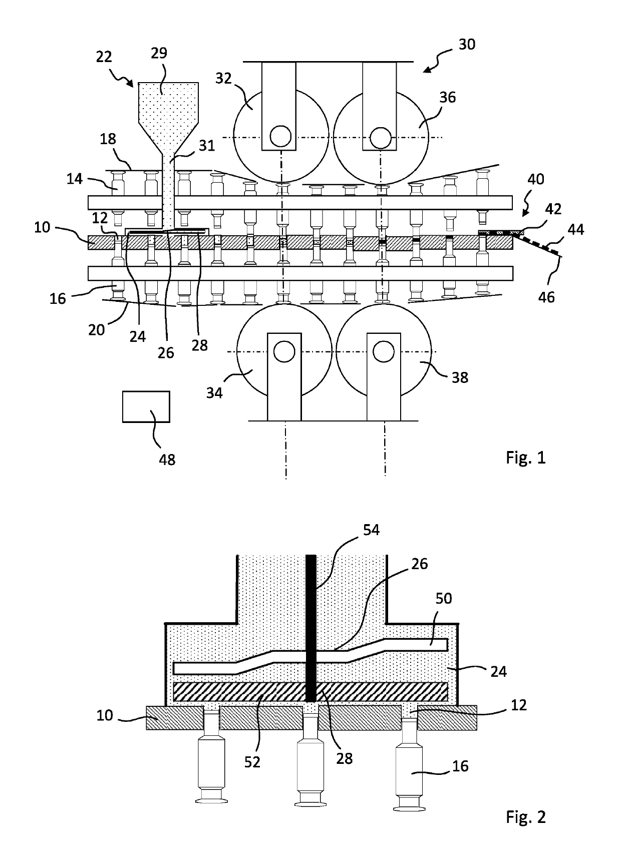
[0023]The rotary press shown in FIGS. 1 and 2, in particular the rotary tablet press, comprises a rotor that is rotationally driven by a rotary drive (not shown) with a die plate 10 which has a plurality of cavities 12. Referring to FIG. 1, the cavities 12 can, for example, be formed by holes in the die plate 10. The rotor further comprises a plurality of top or upper punches 14 and lower or bottom punches 16 that rotate synchronously with the die plate 10. An upper punch 14 and a lower punch 16 are assigned to each cavity 12. The axial movement of the upper punch 14 and lower punch 16, during the rotation of the rotor is controlled by upper control cam elements 18 and lower control cam elements 20. The rotary press moreover comprises a filling apparatus 22 which has a filling chamber 24. As shown in FIG. 1, a first stirrer blade wheel 26 and a second stirrer blade wheel 28 are arranged superimposed in the filling chamber 24. As shown, the stirrer blade wheels 26, 28 are rotatably d...


PUM

PropertyMeasurementUnit
rotary speedaaaaaaaaaa
weightaaaaaaaaaa
breaking strengthaaaaaaaaaa

Abstract

A filling apparatus comprises a filling material reservoir and a filling chamber that is connected to the filling material reservoir with a filling opening configured to dispense filling material into cavities in the rotary press. A first rotatably driven stirrer blade wheel with one or more stirrer blades and a second rotatably driven stirrer blade wheel with one or more stirrer blades are arranged in the filling chamber. The first rotatably driven stirrer blade wheel has at least one of a different geometry, a different direction of rotation, or a different rotary speed, than the second rotatably driven stirrer blade wheel.

Description

CROSS REFERENCE TO RELATED INVENTION[0001]This application is based upon and claims priority to, under relevant sections of 35 U.S.C. § 119, German Patent Application No. 10 2016 110 556.2, filed on Jun. 8, 2016.BACKGROUND[0002]The invention relates to a filling apparatus for filling cavities in a rotary press comprising a filling material reservoir and a filling chamber that is connected to the filling material reservoir and has a filling opening from which the filling material can pass into the cavities of the rotary press.[0003]By means of a filling apparatus, the cavities of a rotary press are filled, metered, and / or pre-compressed with the pressing material to be pressed by the punch of the rotary press. The upper and bottom punches of the rotary press interact in the cavities to press pellets. The quality of the produced pellets depends significantly on the quality of cavity filling. Features that are examined when determining the quality of the produced pellets are, for examp...

Claims


Application Information

Patent Timeline
Patent Type & Authority Patents(United States)
IPC IPC(8): B30B15/30B30B11/00B01F7/16B01F7/00B30B11/08B29C31/04
CPCB01F7/00641B30B15/302B01F7/00291B30B11/003B30B11/08B01F7/166B30B15/308B01F2215/0032B29C31/047B30B15/304B01F27/84B01F27/192B01F27/1125B01F2101/22
Inventor OEZCOBAN, HUESEYINHEINRICH, THOMASEHRICH, THORSTEN
Owner FETTE COMPACTING GMBH
Why Eureka
Try Eureka