Method and device for generating an optimum flight path intended to be followed by an aircraft

a technology of flight path and optimum flight path, which is applied in the direction of process and machine control, instruments, energy saving arrangements, etc., can solve the problems of non-functional limitations of already existing functions for generating non-functional functions, complicated procedures for modification of flight plans,

Active Publication Date: 2019-11-12
AIRBUS OPERATIONS (SAS)
View PDF14 Cites 1 Cited by
  • Summary
  • Abstract
  • Description
  • Claims
  • Application Information

AI Technical Summary

Benefits of technology

[0017]Thus, an aspect of the invention takes account of the geometry of the obstacles by determining the extreme lateral apices. The method and the device make it possible to obtain a rapid convergence by depending on the geometry of the obstacles in order to define a variable heuristic (or rating) adapted to the environmental situation, in such a way as to orient the computation algorithm described in the document FR 2 968 441 directly towards the directions which will make it possible to find a solution whilst limiting the number of positions explored.

Problems solved by technology

Modification of a flight plan, in particular, is often a complicated procedure, necessitating multiple interactions with systems of the aircraft, the final result of which is not totally optimized.
This is notably due, on the one hand, to the difficulties and limitations inherent in the use of published routes and procedures and, on the other hand, to the limitations of the already existing functions for generating non-published flight paths (for example “DIR TO”).
However, the algorithm used does not take account of the location, nor of the geometry of the obstacles in order to anticipate the collisions with the environment.
The method of the algorithm has the feature of being rather robust with regard to the different possible configurations but it sometimes results in a long and unacceptable computing time of an onboard function because the absence of anticipation causes, uselessly with regard to the algorithm, the computation of a large number of positions at each step which result in positions that are inadmissible to the following steps.

Method used


Image

  • Method and device for generating an optimum flight path intended to be followed by an aircraft
  • Method and device for generating an optimum flight path intended to be followed by an aircraft
  • Method and device for generating an optimum flight path intended to be followed by an aircraft

Examples


Embodiment Construction

[0052]The continuation of the description will refer to the abovementioned figures.

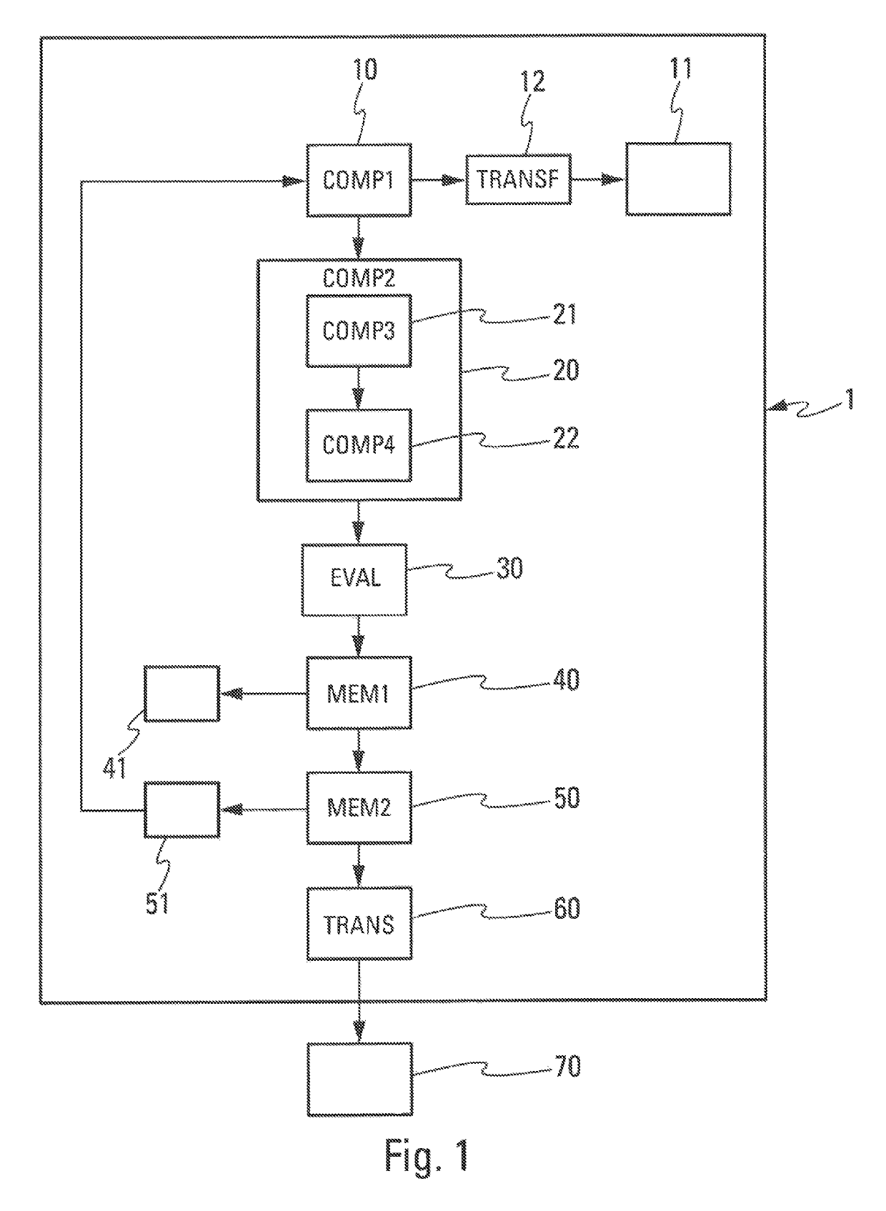
[0053]FIG. 1 shows an embodiment of a device 1 for generating at least an optimum flight path 15 (FIG. 8) intended to be followed by an aircraft (AC).

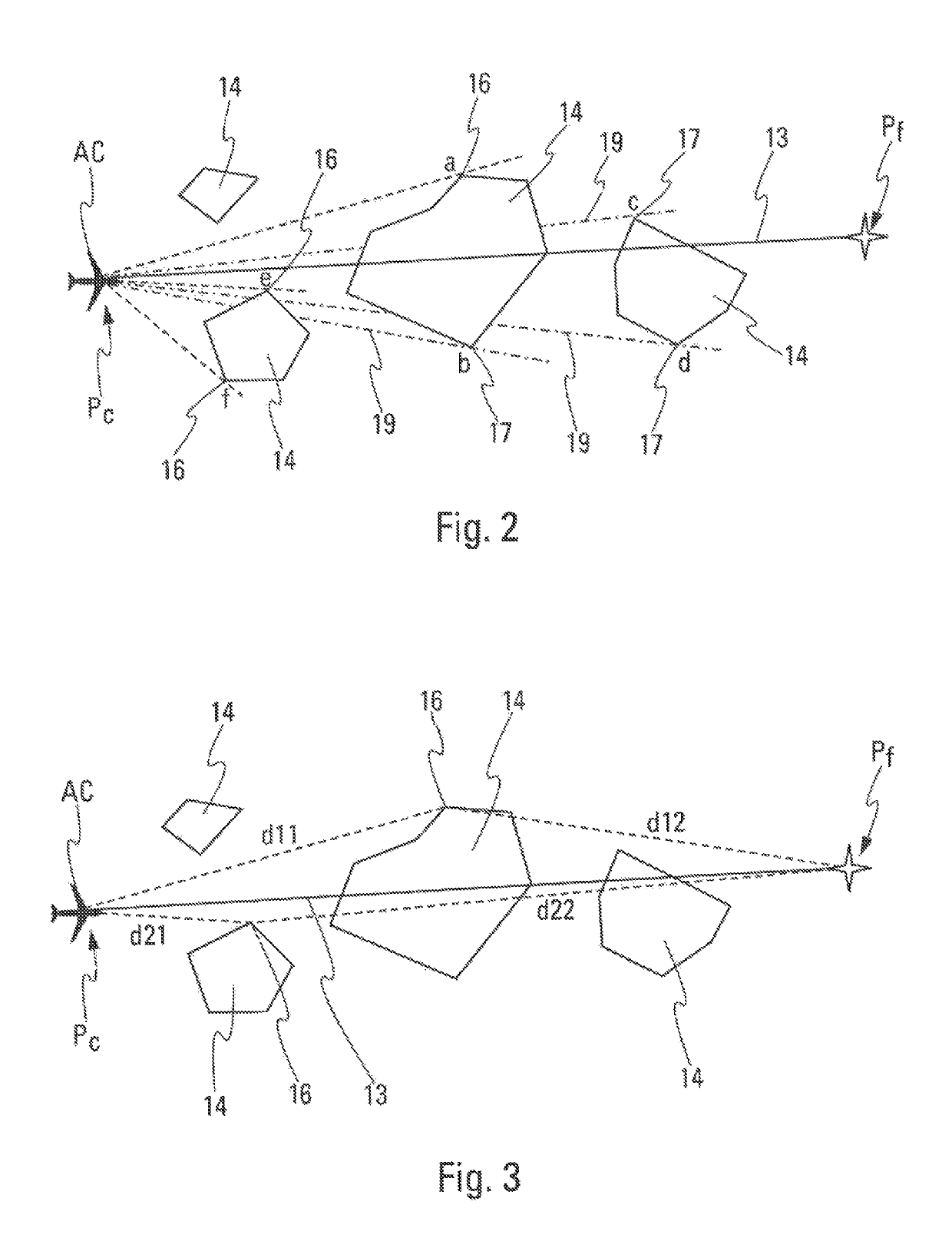
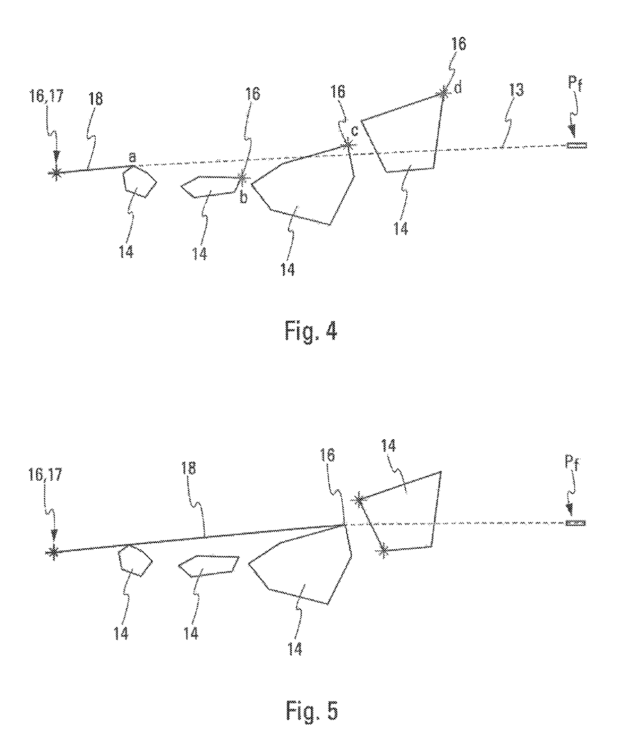
[0054]The optimum flight path 15 is defined between a current point Pc and a target point Pf (FIG. 2).

[0055]It comprises a lateral flight path and a vertical flight path.

[0056]The current point Pc corresponds to the current position of the aircraft AC starting from which the optimum flight path 15 is determined. The target point Pf corresponds to the final position of the optimum flight path 15.

[0057]The said device (FIG. 1) comprises a database 11 comprising data relative to obstacles 14.

[0058]The data relative to obstacles 14 correspond to a set of data comprising sets of points representative of obstacles. Each obstacle 14 is defined by a set of points in space. In general, the set of points for an obstacle 14 forms a polyhedron. A polyhedron forming ...


PUM


Abstract

A device includes a database including data related to obstacles, a first determination module for determining at least one obstacle intercepted by a direct flight path connecting an initial point to the target point, a second determination module for determining at least one lateral extreme apex of at least one intercepted obstacle, an evaluation module for assigning a rating to each section corresponding to a segment between a lateral extreme apex and the initial point, a storage module for storing in a memory the section corresponding to the optimum extreme apex having the best rating, the optimum flight path corresponding to all of the sections stored in the memory, the preceding modules being used iteratively, the device further including a transmission module for transmitting the optimum flight path to a user device.

Description

FIELD OF THE INVENTION[0001]The present invention relates to a method and a device for generating an optimum flight path intended to be followed by an aircraft, in particular a transport aircraft.[0002]The purpose of the present invention is to generate in real time, with the help of onboard means, optimized flight paths which are flyable in constrained dynamic environments, that is to say in environments that are likely to contain objects or obstacles which the aircraft must avoid colliding with. These objects or these obstacles notably correspond to moving objects such as areas of meteorological disturbances, stormy areas for example, or other aircraft.BACKGROUND OF THE INVENTION[0003]It is known that management of the flight path of an aircraft is generally left under the control of an onboard flight management system. Modification of a flight plan, in particular, is often a complicated procedure, necessitating multiple interactions with systems of the aircraft, the final result ...

Claims


Application Information

Patent Timeline
Patent Type & Authority Patents(United States)
IPC IPC(8): G08G5/00G08G5/04G01C21/20G05D1/00
CPCG08G5/0021G08G5/045G08G5/006G08G5/0078G08G5/0039G05D1/0005G08G5/0034G01C21/20G08G9/02
Inventor MERE, JEAN-CLAUDE
Owner AIRBUS OPERATIONS (SAS)
Why Eureka
Try Eureka