
Cam phaser

a phaser and cam technology, applied in the direction of machines/engines, mechanical equipment, engine components, etc., can solve the problems of reducing the cost of finishing processes, affecting the quality of finished products, and affecting the cost effectiveness of production, so as to reduce the complexity of finishing and cost effective production

Active Publication Date: 2019-11-19
ECO HLDG 1 GMBH
View PDF5 Cites 0 Cited by
  • Summary
  • Abstract
  • Description
  • Claims
  • Application Information

AI Technical Summary

Benefits of technology

This approach simplifies the finishing process, reduces costs, and maintains precision while minimizing elastic deformation and leakage, ensuring reliable operation under varying conditions.

Problems solved by technology

The finishing processes are expensive and have their quality risks which are only increased by handling steps arranged there between.
The proposed multi component configuration of the stator or the rotor is considered detrimental due to the number of components and the complex joining method.

Method used


Image

  • Cam phaser
  • Cam phaser
  • Cam phaser

Examples


Embodiment Construction

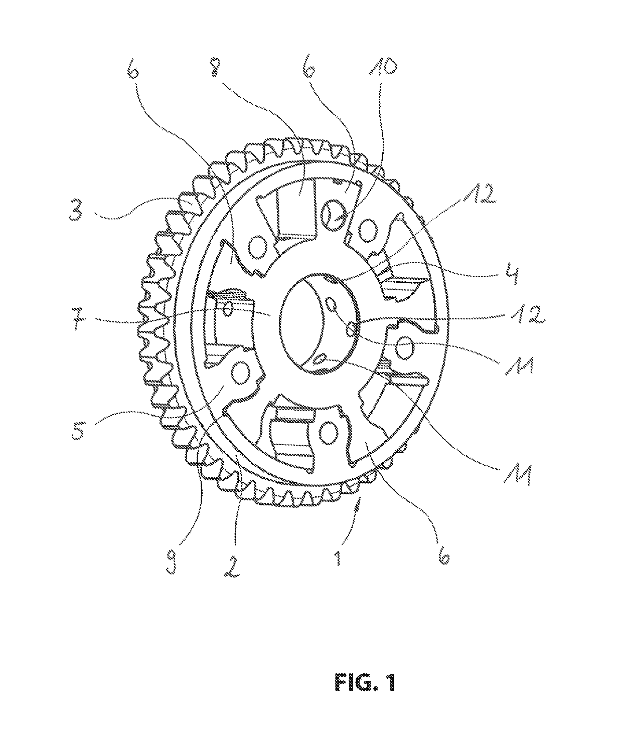
[0023]FIG. 1 illustrates a known cam phaser 1 configured to adjust an angular relationship between a crank shaft and a cam shaft during operations of an internal combustion engine. A relative rotation of the non-illustrated cam shaft adjusts opening and closing timing of the gas control valves so that the internal combustion engine delivers optimum power at a respective speed. The cam phaser 1 thus facilitates a continuously variable adjustment of the cam shaft relative to the crank shaft.

[0024]The cam phaser 1 includes a cylindrical stator 2 which is connected torque proof with a gear 3. In the embodiment the gear 3 is a sprocket over which a chain is run that is not illustrated in detail. The gear 3, however, can also be a timing belt cog over which a drive belt is run that forms the drive element. The stator 2 is operatively connected with the crank shaft through the drive element and the gear 3 in a known manner.

[0025]In this embodiment the stator 2 and the gear 3 are integrally...


PUM


Abstract

A cam phaser including a stator that is driven by a crank shaft of an internal combustion engine; and a rotor that is connectable torque proof with a cam shaft of the internal combustion engine and that includes plural blades that protrude radially outward from a rotor hub, wherein operating chambers arranged between the stator and the rotor are divided into pressure cavities by the blades, wherein the stator and the rotor are configured as sintered components, wherein displacement recesses are provided on axially configured faces of the stator and / or of the rotor wherein material is configured to flow into the displacement recesses during a deforming finishing of the faces.

Description

RELATED APPLICATIONS[0001]This application is a continuation of International Application PCT / EP 2016 / 067660 which claims priority from German Patent Application DE 10 2015 112 442.4 filed on Jul. 30, 2015, both of which are incorporated in their entirety by this reference.FIELD OF THE INVENTION[0002]The invention relates to a cam phaser including a stator that is driven by a crank shaft of an internal combustion engine, a rotor that is connectable torque proof with a cam shaft of the internal combustion engine and that includes plural blades protruding radially outward from a rotor hub, wherein operating chambers arranged between the stator and the rotor that are divided into pressure cavities by the blades and wherein the stator and the rotor are configured as sintered components.BACKGROUND OF THE INVENTION[0003]Cam phasers are used modern internal combustion engines to optimize consumption and power parameters and are used for controlling opening and closing timing of the gas con...

Claims


Application Information

Patent Timeline
Patent Type & Authority Patents(United States)
IPC IPC(8): F01L1/34F01L1/344
CPCF01L1/3442F01L2820/00F01L2001/34479F01L2101/02F01L2103/00F01L2301/02F01L2303/00
Inventor HEILIG, MARKUSHENTSCH, FLORIANSCHULZE, DIETMAR
Owner ECO HLDG 1 GMBH
Learn More