
Method and apparatus for generating a magnetic resonance image with radio collection of magnetic resonance data to avoid image artifacts

a magnetic resonance and data collection technology, applied in the field of reconstruction of magnetic resonance images, can solve the problem that the radial collection of mr data is more sensitive to system failures, and achieve the effect of not needing to extend the scan tim

Active Publication Date: 2019-12-03
SIEMENS HEALTHCARE GMBH
View PDF6 Cites 0 Cited by
  • Summary
  • Abstract
  • Description
  • Claims
  • Application Information

AI Technical Summary

Benefits of technology

The present invention improves the reconstruction of MR images by reducing the sensitivity to interference caused by metal parts and off-resonance artifacts. By avoiding antiparallel readout directions and phase cancellations, the invention achieves better image quality without the need to extend the scan time. The invention also eliminates artifacts that are present in only one of the MR images that are reconstructed from the same MR data.

Problems solved by technology

However, the radial collection of MR data is more sensitive to system failures such as gradient delays and off-resonance effects.

Method used


Image

  • Method and apparatus for generating a magnetic resonance image with radio collection of magnetic resonance data to avoid image artifacts
  • Method and apparatus for generating a magnetic resonance image with radio collection of magnetic resonance data to avoid image artifacts
  • Method and apparatus for generating a magnetic resonance image with radio collection of magnetic resonance data to avoid image artifacts

Examples


first embodiment

[0072]FIG. 4 shows a flowchart of the method according to the invention.

[0073]In step S1, a primary readout direction and with it an associated field of a solid angle (three-dimensional case) or angular field (two-dimensional case) is determined, in the center of which is the primary readout direction. In step S2 trajectories are determined and in step S3 the MR data is collected along these trajectories.

[0074]Steps S4 to S6 examine the MR data which is used for the reconstruction of the MR image. To this end, step S4 examines whether the readout direction of the trajectory is within the field of a solid angle defined in step S1 for each trajectory. In step S5 the MR data are identified as the only MR data to be taken into consideration for the reconstruction of the MR image if this is the case.

[0075]If it is recognized that all the trajectories have been examined in step S6, the MR image is reconstructed in step S7 on the basis of only the MR data identified in step S5.

second embodiment

[0076]FIG. 5 shows a flowchart of the method according to the invention.

[0077]In step S11, as in step S1 (FIG. 4), a primary readout direction and with it an associated field of a solid angle (three-dimensional case) or angular field (two-dimensional case) is determined, in the center of which is the primary readout direction. Step S12 determines trajectories and the sequence in which these trajectories are to be scanned.

[0078]Subsequently, steps S13 to S15 are performed for all the predetermined trajectories. Step S13 examines whether the readout direction of the respective trajectory is outside the field of a solid angle and / or angular field in step S11. The original readout direction in step S14 is only inverted or reversed if this is the case. Subsequently, MR data is collected in the readout direction along the respective trajectory in step S15.

[0079]Step S16 examines whether all the trajectories determined in step S12 have been scanned. If so, an MR image is reconstructed on t...


PUM


Abstract

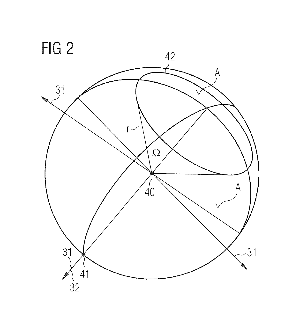
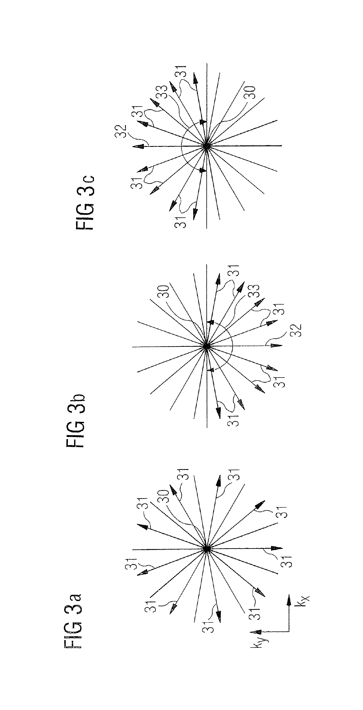
For the creation of a magnetic resonance (MR) image of a predetermined volume section of an object of investigation, MR data of the volume section are collected along radial trajectories, and each trajectory is assigned a readout direction in which the MR data are collected along the respective trajectory. The MR image is reconstructed on the basis of the collected MR data. In the reconstruction, only MR data are taken into consideration that were collected along trajectories with a readout direction restricted to the field of a solid angle that is defined by a partial surface of a sphere. The partial surface (A) at most corresponds to 75% of the total surface of the sphere.

Description

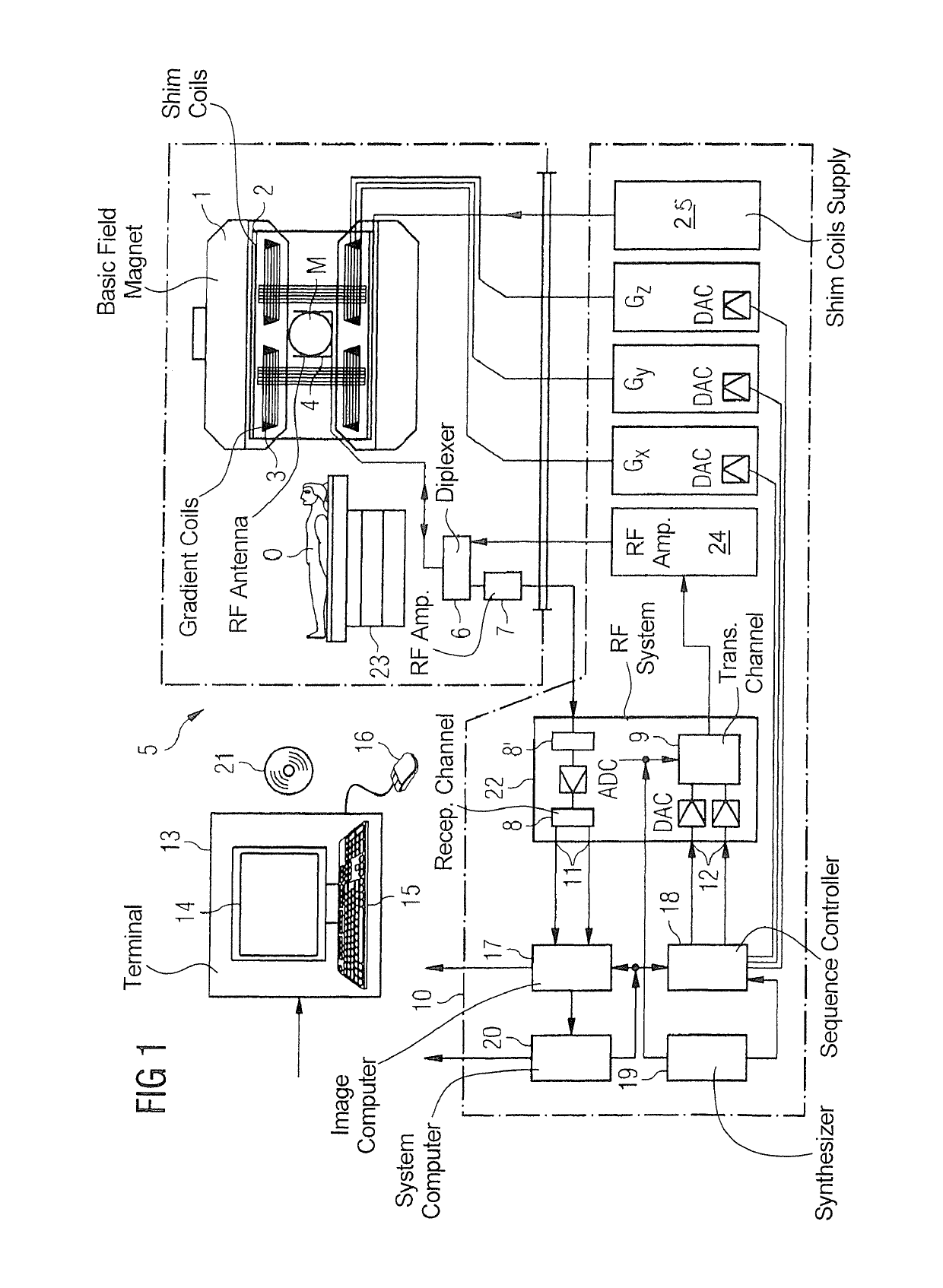
BACKGROUND OF THE INVENTION[0001]Field of the Invention[0002]The present invention concerns the reconstruction of a magnetic resonance (MR) image from radial collection of MR data in a manner that avoids artifacts (in particular, artifacts caused by metal parts).[0003]Description of the Prior Art[0004]In magnetic resonance imaging, raw data (magnetic resonance measurement data) are acquired from a subject by the operation of a magnetic resonance scanner in which the subject is situated. The acquired raw data are entered as complex numbers at respective data points of a memory. This collection of raw data in the memory is known as k-space data. The entry of the raw data at the respective data points of the memory is known as “scanning” k-space, or scanning a k-space memory. The path composed of data points along which the raw data are successively entered in k-space is known as a “k-space trajectory.”[0005]The k-space data are then transformed into image data, typically by operation ...

Claims


Application Information

Patent Timeline
Patent Type & Authority Patents(United States)
IPC IPC(8): G01R33/48G01R33/483
CPCG01R33/4826G01R33/4824G01R33/483
Inventor GEPPERT, CHRISTIANGRIMM, ROBERT
Owner SIEMENS HEALTHCARE GMBH
Learn More