Intelligent ladar system with low latency motion planning updates

a technology of intelligent ladars and motion planning updates, applied in the direction of condensers, complex mathematical operations, instruments, etc., can solve problems such as motion decision-making delays

Active Publication Date: 2019-12-03
AEYE INC
View PDF161 Cites 40 Cited by
  • Summary
  • Abstract
  • Description
  • Claims
  • Application Information

AI Technical Summary

Benefits of technology

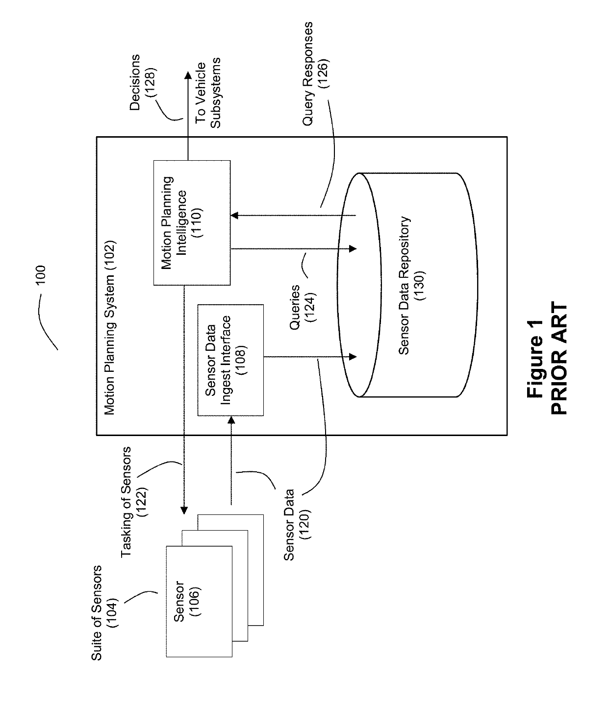
[0004]Safe autonomy in vehicles, whether airborne, ground, or sea-based, relies on rapid precision, characterization of, and rapid response to, dynamic obstacles. A conventional approach to autonomous obstacle detection and motion planning for moving vehicles is shown by FIG. 1. The system 100 for use with a vehicle comprises a motion planning system 102 in combination with a suite 104 of sensors 106. The sensors 106 in the suite 104 provide the motion planning system 102 with sensor data 120 for use in the obstacle detection and motion planning process. Sensor data ingest interface 108 within the motion planning system 102 receives the sensor data 120 from the sensors 106 and stores the sensor data 120 in a sensor data repository 130 where it will await processing. Motion planning intelligence 110 within the motion planning system 102 issues read or query commands 124 to the sensor data repository 130 and receives the requested sensor data as responses 126 to the queries 124. The intelligence 110 then analyzes this retrieved sensor data to make decisions 128 about vehicle motion that are communicated to one or more other vehicle subsystems. The motion planning intelligence 110 can also issue tasking commands 122 to the sensors 106 to exercise control over sensor data acquisition.
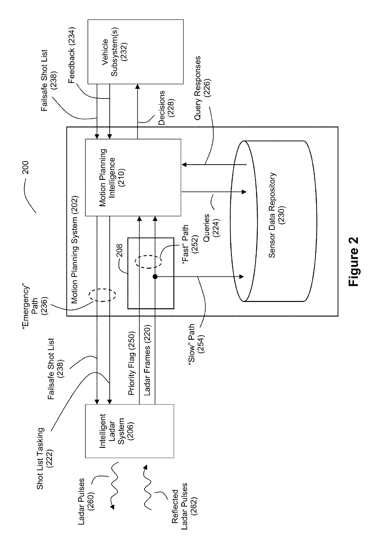
[0006]As a technical improvement in the art, the inventors disclose a more collaborative model of decision-making as between the one or more of the sensors 106 and the motion planning system 102, whereby some of the intelligence regarding object and anomaly detection are moved into one or more of the sensors 106. In the event that the intelligent sensor detects an object of concern from the sensor data, the intelligent sensor can notify the motion planning system 102 via priority messaging or some other “fast path” notification. This priority messaging can serve as a vector interrupt that interrupts the motion planning system 102 to allow for the motion planning system 102 to quickly focus on the newly detected threat found by the intelligent sensor. Thus, unlike the master-slave relationship shown by FIG. 1, an example embodiment of a new faster approach to sensor-based motion planning can employ more of a peer-to-peer model for anomaly detection coupled with a capability for one or more intelligent sensors to issue priority messages / interrupts to the motion planning system. With this model, threats detected by the intelligent sensor can be pushed to the top of the data stack under consideration by the motion planning system 102.
[0007]The inventors also disclose a “fast path” for sensor tasking where threat detection by the intelligent sensor can trigger the intelligent sensor to insert new shot requests into a pipeline of sensor shots requested by the motion planning system. This allows the intelligent sensor to quickly obtain additional data about the newly detected threat without having to wait for the slower decision-making that would be produced by the motion planning system.
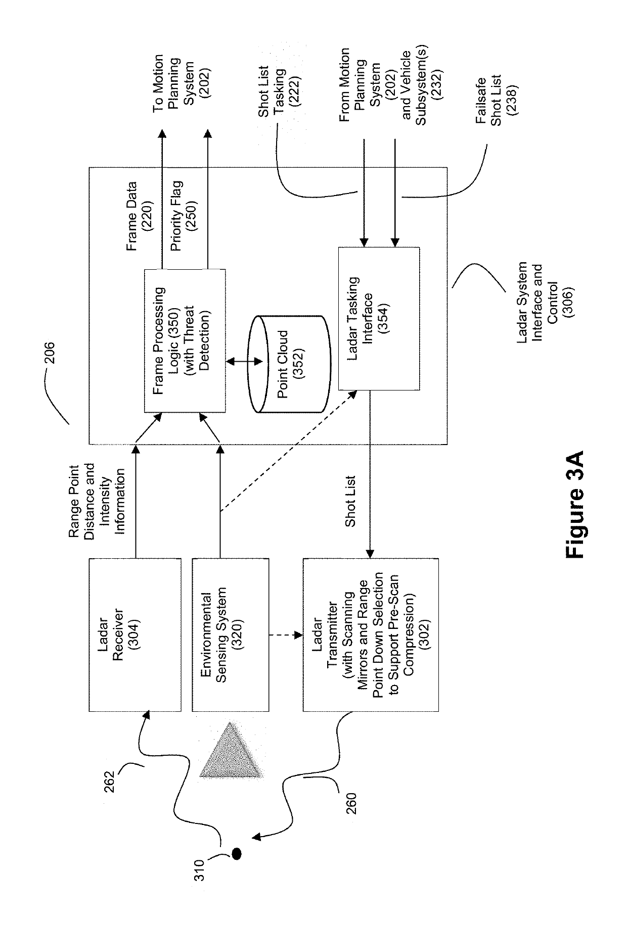
[0008]Furthermore, in an example embodiment, the inventors disclose that the intelligent sensor can be a ladar system that employs compressive sensing to reduce the number of ladar shots required to capture a frame of sensor data. When such a ladar system is combined with the collaborative / shared model for threat detection, where the ladar system can issue “fast path” priority messages to the motion planning system regarding possible threats, latency is further reduced. As used herein, the term “ladar” refers to and encompasses any of laser radar, laser detection and ranging, and light detection and ranging (“lidar”).
[0009]Further still, the inventors disclose example embodiments where a camera is co-bore sited with a ladar receiver to provide low latency detection of objects in a field of view for a ladar system. A frequency-based beam splitter can be positioned to facilitate sharing of the same field of view by the ladar receiver and the camera.
[0010]Furthermore, the inventors also disclose example embodiments where tight clusters of overlapping ladar pulse shots are employed to facilitate the computation of motion data of objects on an intraframe basis. This allows the development of robust kinematic models of objects in a field of view on a low latency basis.

Problems solved by technology

These processing burdens result in motion decision-making delays arising from the amount of time it takes for the motion planning system 102 to ingest, store, retrieve, and analyze the sensor data.

Method used


Image

  • Intelligent ladar system with low latency motion planning updates
  • Intelligent ladar system with low latency motion planning updates
  • Intelligent ladar system with low latency motion planning updates

Examples


Embodiment Construction

[0031]FIG. 2 discloses an example system 200 for vehicle autonomy with respect to motion planning. In this example, the motion planning system 202 interacts with a sensor such as an intelligent ladar system 206 in a manner where the intelligent ladar system 206 is able to provide fast path notifications regarding detected threats. Unlike the conventional master-slave hierarchical relationship between a motion planning system and sensor, the example embodiment of FIG. 2 employs a collaborative model of decision-making as between an intelligent ladar system 206 and the motion planning system 202, whereby some of the intelligence regarding object and anomaly detection is positioned in the intelligent ladar system 206. Also, it should be understood that the system 200 may include sensors other than intelligent ladar system 206 that provide information to the motion planning system 202 (e.g., one or more cameras, one or more radars, one or more acoustic sensors, one or more vehicle telem...


PUM


Abstract

Systems and methods are disclosed for vehicle motion planning where a sensor, such as a ladar system, is used to detect threatening or anomalous conditions within the sensor's field of view so that priority warning data about such conditions can be inserted at low latency into the motion planning loop of a motion planning computer system for the vehicle. The ladar system can perform compressive sensing to target the field of view with a plurality of ladar pulses.

Description

CROSS-REFERENCE AND PRIORITY CLAIM TO RELATED PATENT APPLICATIONS[0001]This patent application claims priority to U.S. provisional patent application 62 / 693,078, filed Jul. 2, 2018, and entitled “Intelligent Ladar System with Low Latency Motion Planning Updates”, the entire disclosure of which is incorporated herein by reference.[0002]This patent application also claims priority to U.S. provisional patent application 62 / 558,937, filed Sep. 15, 2017, and entitled “Intelligent Ladar System with Low Latency Motion Planning Updates”, the entire disclosure of which is incorporated herein by reference.[0003]This patent application is also related to (1) U.S. patent application Ser. No. 16 / 106,374, filed this same day, and entitled “Ladar Receiver with Co-Bore Sited Camera”, (2) U.S. patent application Ser. No. 16,106,406, filed this same day, and entitled “Low Latency Intra-Frame Motion Estimation Based on Clusters of Ladar Pulses”, and (3) U.S. patent application Ser. No. 16,106,441, fil...

Claims


Application Information

Patent Timeline
Patent Type & Authority Patents(United States)
IPC IPC(8): G06F17/10G01S17/89G01S17/10G01S7/486G01S7/484G01S17/02G01S7/481G01S17/42G01S17/93G08G1/16G01S7/4861G01S17/86G01S17/931
CPCG01S17/936G01S7/4817G01S17/023G01S17/42G01S17/10G01S7/484G01S17/89G01S7/4861G01S7/4814G01S17/86G01S17/931G01S7/4811G02B19/0028G02B19/0085G02B26/108
Inventor DUSSAN, LUIS CARLOSSTEINHARDT, ALLANBENSCOTER, JOEL DAVIDGREENE, JORDAN SPENCER
Owner AEYE INC
Why Eureka
Try Eureka