Motors with damper for reducing vibration and noise of rotor

a technology of rotor and damper, which is applied in the direction of shock absorbers, mechanical devices, windings, etc., can solve the problems of degrading the efficiency of the motor, achieve the effect of reducing the vibration and noise of the rotor, and maximising the maintenance of the conventional structur

Active Publication Date: 2019-12-03
HYO SEONG ELECTRIC
View PDF4 Cites 1 Cited by
  • Summary
  • Abstract
  • Description
  • Claims
  • Application Information

AI Technical Summary

Benefits of technology

[0017]An object of the present invention is to provide a motor equipped with dampers for reducing the vibration and noise of a rotator, which provides mobility against vibration shock in order to prevent the vibration shock from being directly applied when a rotator is rotated.
[0018]An object of the present invention is to provide a motor equipped with dampers for reducing the vibration and noise of a rotator, which can maximally maintain a conventional structure without a significant change in the overall structure of a conventional motor while suppressing the generation of vibration and noise by cancelling vibration and noise generated when a rotator is rotated.
[0019]An object of the present invention is to provide a motor equipped with dampers for reducing the vibration and noise of a rotator, which can cancel vibration and noise generated by a rotator without a significant change in the overall structure of a conventional motor, so that cost attributable to a change in design is not incurred, thereby providing economic efficiency, and which has a simple structure, so that the present invention can be easily applied to various types of motors, thereby providing high applicability.

Problems solved by technology

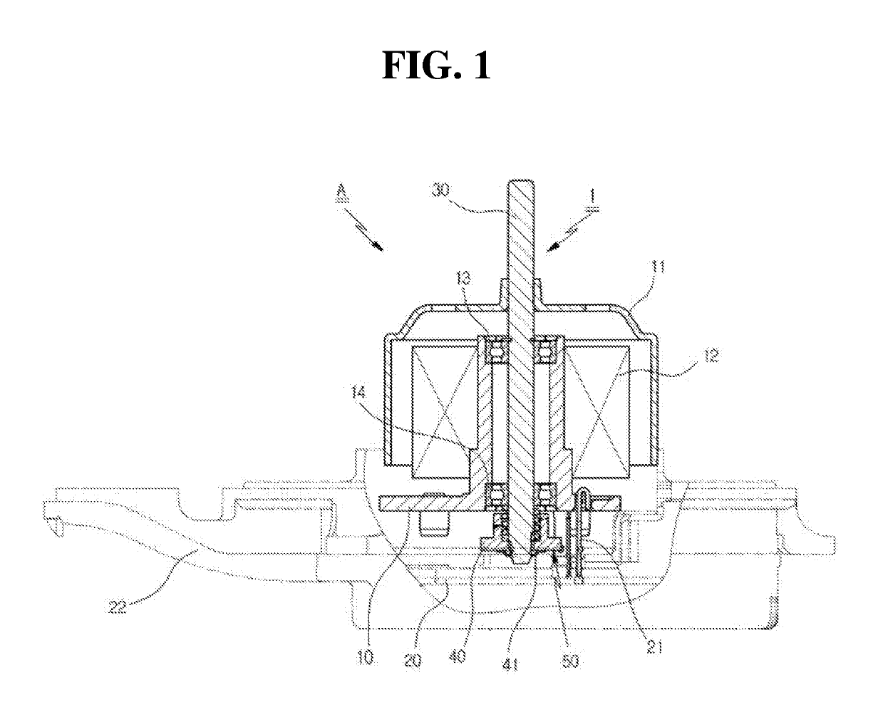
However, in the motor having the above-described structure, the stator block 10 is provided in the state of being in contact with the upper cover and the lower cover, and thus a problem arises in that vibration shock is directly applied when the rotator is rotated, which results in a problem in which the efficiency of a motor is degraded.

Method used


Image

  • Motors with damper for reducing vibration and noise of rotor
  • Motors with damper for reducing vibration and noise of rotor
  • Motors with damper for reducing vibration and noise of rotor

Examples


Embodiment Construction

[0032]Advantages and features of the present invention and methods for achieving them will be apparent upon referring to embodiments described later in detail together with the accompanying drawings. However, the present invention is not limited to the embodiments disclosed below, but may be embodied in various different forms. These embodiments are provided merely to make the disclosure of the present invention complete and fully convey the scope of the present invention to a person having ordinary knowledge in the art to which the present invention pertains. The present invention is defined only based on the scopes of the claims. The same reference numerals designate the same elements throughout the present specification.

[0033]In the description of the embodiments of the present invention, when it is determined that a detailed description of a related well-known function or element may make the gist of the present invention obscure, the detailed description will be omitted. The te...


PUM

PropertyMeasurementUnit
outer circumferencesaaaaaaaaaa
elasticityaaaaaaaaaa
energy efficiencyaaaaaaaaaa

Abstract

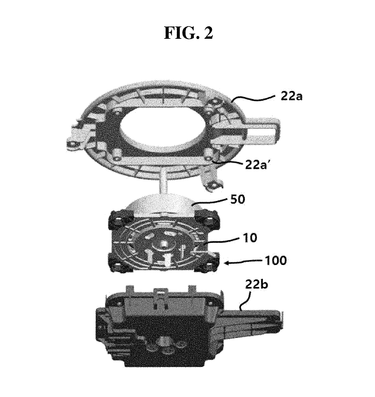
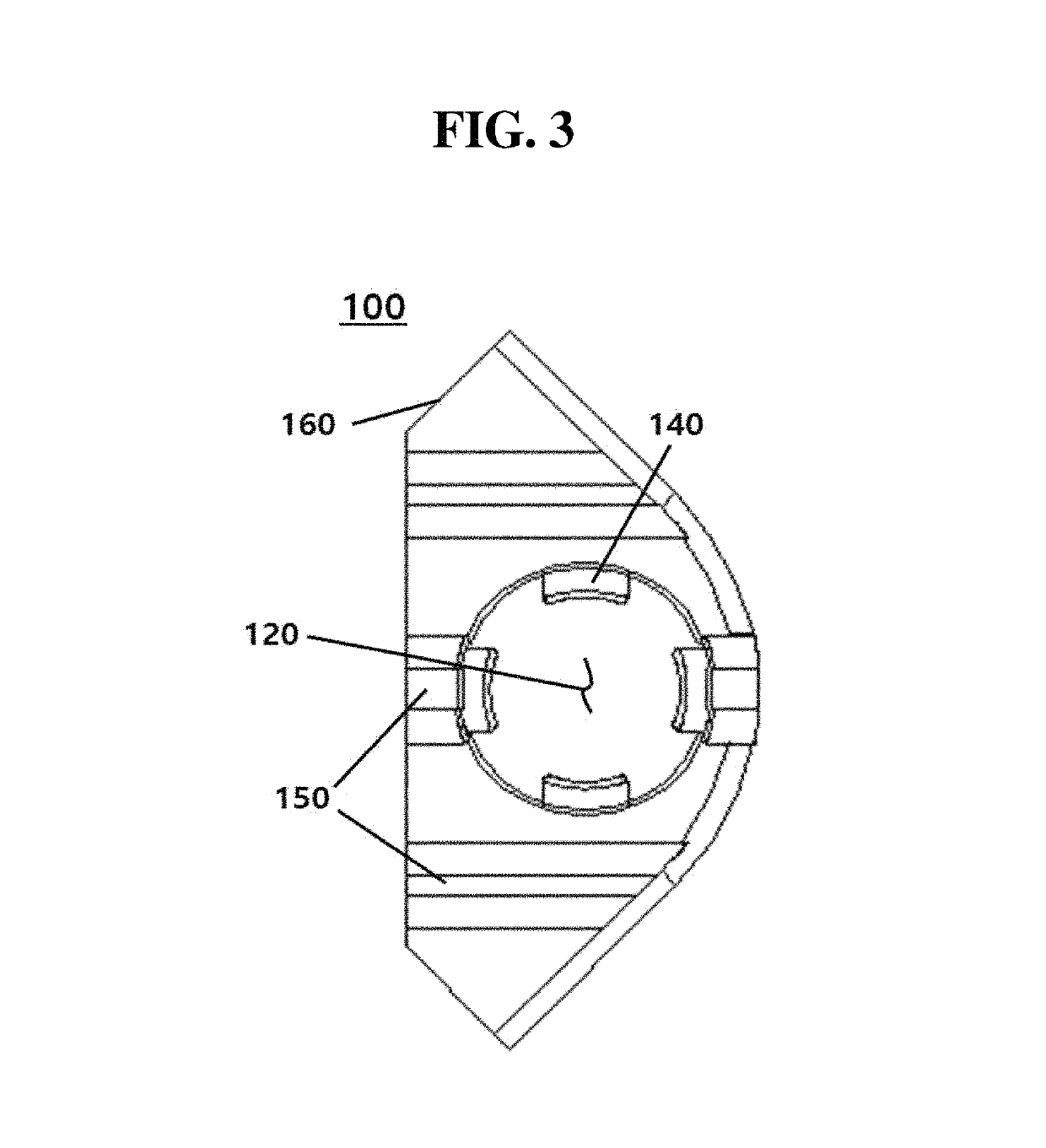
A motor equipped with dampers for reducing the vibration and noise of a rotator is disclosed. The motor includes: a stator block configured such that a core around is fastened and installed in the upper outer portion of the inside of a cover; a printed circuit board (PCB) fastened and installed below the stator block inside a motor housing; a shaft installed inside the stator block; and a rotor configured to include a magnet; wherein the motor housing includes an upper cover and a lower cover, a plurality of fastening portions is formed on the upper cover, and a plurality of fastening depressions is formed on the lower cover; and wherein the motor further includes dampers configured to receive and accommodate the fastening portions, to be inserted over side surfaces of the base portion of the stator block, and to cancel vibration and noise.

Description

BACKGROUND[0001]1. Technical Field[0002]The present disclosure relates to a motor equipped with dampers for reducing the vibration and noise of a rotator, and more specifically to a motor equipped with dampers for reducing the vibration and noise of a rotator, in which a stator block provided in the motor is provided with dampers for preventing shock and noise, thereby reducing vibration and noise generated when the rotator is rotated.[0003]2. Description of the Related Art[0004]Unless otherwise indicated herein, the content described in this section is not prior art to the claims in this application, and is not admitted to be prior art by inclusion in this section.[0005]Recently, in order to increase energy efficiency, three-phase brushless DC motors, which are controlled by inverters, have been increasingly used in household appliances, such as automobiles, air conditioners, washing machines.[0006]A brushless DC (BLDC) motor is also called a commutatorless motor. A BLDC motor is a...

Claims


Application Information

Patent Timeline
Patent Type & Authority Patents(United States)
IPC IPC(8): H02K5/24F16F3/087F16F15/08F16F1/36
CPCF16F15/08F16F3/0876H02K5/24F16F1/36F16F2224/025F16F1/376H02K11/33H02K2203/03H02K29/00
Inventor JUNG, JINGEUN
Owner HYO SEONG ELECTRIC
Why Eureka
Try Eureka