
Analytical cell and method of producing the same

a technology of analytic cells and cells, applied in secondary cells, secondary cell servicing/maintenance, sustainable manufacturing/processing, etc., can solve the problems of difficult to accurately position the substrates with respect to each other, the distance between the substrates may deviate from a distance value, and the positional displacement of the substrates may occur, etc. achieve the effect of maintaining the position of the substrate and the distance between the substrates, reducing the difficulty of positioning the substrates, and reducing the difficulty

Active Publication Date: 2019-12-10
HONDA MOTOR CO LTD
View PDF16 Cites 1 Cited by
  • Summary
  • Abstract
  • Description
  • Claims
  • Application Information

AI Technical Summary

Benefits of technology

[0017]A main object of the present invention is to provide an analytical cell having excellent analysis accuracy, by making it possible to position substrates with each other and set the distance therebetween easily and highly accurately, and to maintain the positioning and the distance.
[0028]In the above method of producing the analytical cell, preferably, the solid state joint is formed to seal at least one side of the overlapping portion. In this case, the production steps can be simplified, and thus, it becomes possible to obtain the analytical cell even more efficiently.

Problems solved by technology

Therefore, in the case where the machining accuracy with respect to the pocket is not sufficient, it is difficult to position the substrates with respect to each other accurately.
Therefore, there is a concern that positional displacement of the substrates may occur due to the pressure applied to the analytical cell through the O-rings, e.g., at the time of attaching the holder lid to the holder body.
In such a case, there is a concern that the distance between the substrates may deviate from a distance value which has been determined beforehand based on the thickness, etc. of the spacer.
In particular, since observation of the analytical cell by an electron microscope is performed under a high vacuum atmosphere, due to the influence of pressure change caused when evacuation is performed from the atmospheric pressure, the positional displacement between the substrates and changes in the distance between the substrates tend to become large.

Method used


Image

  • Analytical cell and method of producing the same
  • Analytical cell and method of producing the same
  • Analytical cell and method of producing the same

Examples


Embodiment Construction

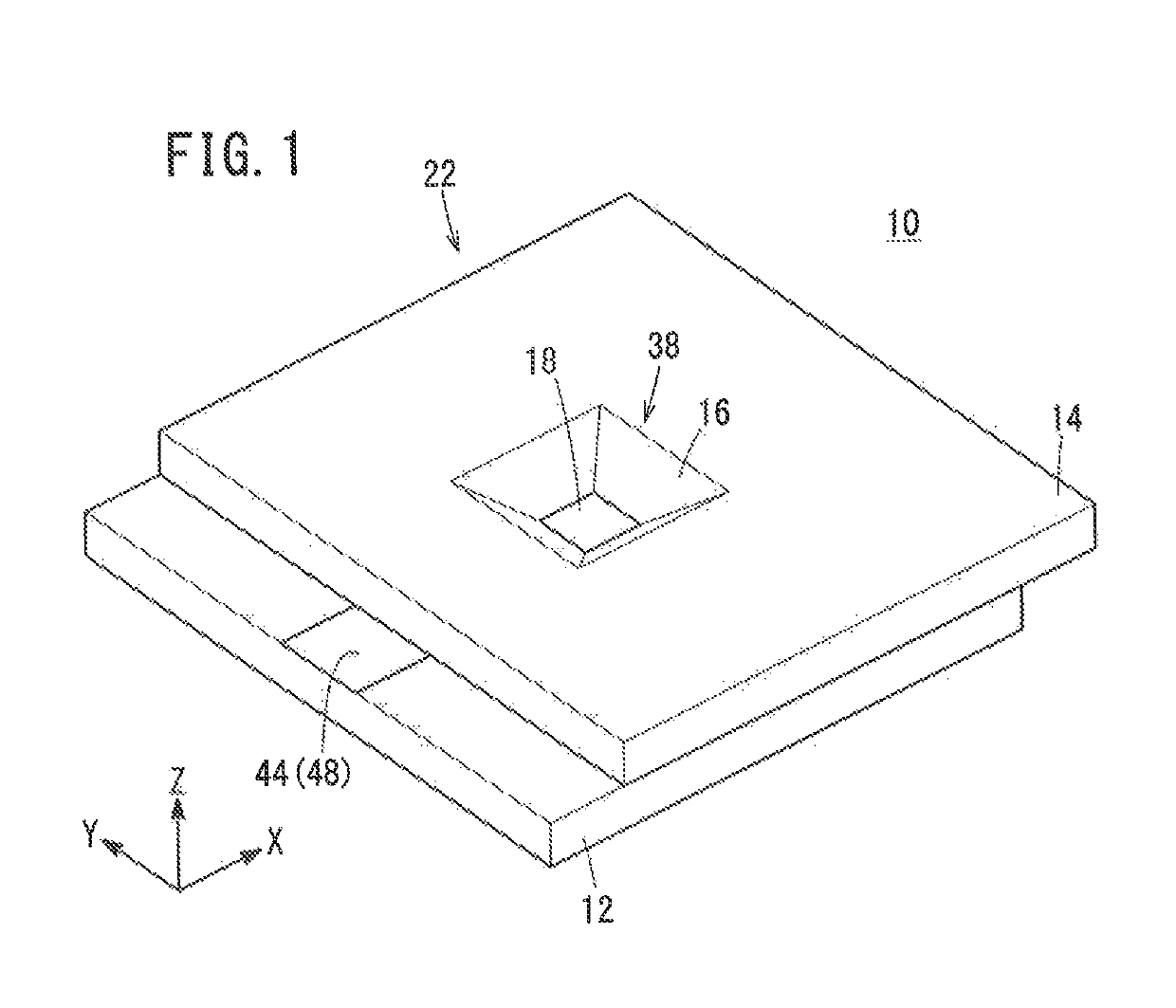
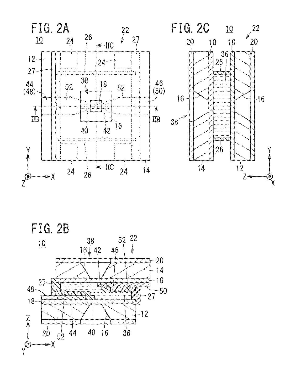
[0060]Hereinafter, preferred embodiments of an analytical cell and a method of producing the analytical cell, according to the present invention, will be described in detail with reference to the accompanying drawings.

[0061]The analytical cell is suitable for use, e.g., in performing an analysis of electrode reactions in a negative electrode active material and a positive electrode active material by use of electron beam transmission in various types of analytical equipment. For example, the analytical equipment may be a transmission electron microscope (TEM). In this case, the analytical cell is accommodated in a front end of a holder, and an observation process is performed. Further, for example, the analytical cell may be any of a metal ion secondary cell of lithium, sodium, or the like, a nickel-hydrogen cell, an alkaline-manganese cell, a metal ion air cell, a metal ion all solid cell, etc., and a fuel cell such as a solid polymer electrolyte fuel cell. Hereinafter, examples of...


PUM

PropertyMeasurementUnit
sizeaaaaaaaaaa
sizeaaaaaaaaaa
temperatureaaaaaaaaaa

Abstract

An analytical cell includes a first substrate and a second substrate each having a through hole extending in a thickness direction thereof. The first substrate and the second substrate are partially overlapped with each other to form an overlapping portion. In the overlapping portion, a solid state joint is formed by solid state bonding of a first solid portion protruding from the first substrate and a second solid portion protruding from the second substrate, whereby the first substrate and the second substrate are spaced from each other by a predetermined distance, and joined together in a state where the first substrate and the second substrate are positioned to form an observation window. At the observation window, the through holes of the first substrate and the second substrate face each other, and an electron beam is transmitted through the observation window.

Description

CROSS-REFERENCE TO RELATED APPLICATION[0001]This application is based upon and claims the benefit of priority from Japanese Patent Application No. 2015-132566 filed on Jul. 1, 2015, the contents of which are incorporated herein by reference.BACKGROUND OF THE INVENTION[0002]Field of the Invention[0003]The present invention relates to an analytical cell suitable for use, e.g., in an electrode reaction analysis in analytical equipment, and a method of producing the analytical cell.[0004]Description of the Related Art[0005]As is well known, in an electric cell, a negative electrode active material and a positive electrode active material undergo electrode reactions in a charge-discharge process. In recent years, such electrode reactions have been analyzed during the charging / discharging process using analytical equipment. For example, an analytical cell that can be observed by a transmission electron microscope (TEM) has been proposed in In-situ Electron Microscopy of Electrical Energy ...

Claims


Application Information

Patent Timeline
Patent Type & Authority Patents(United States)
IPC IPC(8): H01J37/20H01M10/42G01N23/2204H01M4/04
CPCH01M10/4285G01N23/2204H01J37/20H01J2237/2003H01J2237/2802Y02E60/10Y02P70/50
Inventor MAEBASHI, TAKANORIKURIYAMA, NARIAKIFUJIWARA, YOSHIYA
Owner HONDA MOTOR CO LTD
Learn More