Eureka AIR delivers breakthrough ideas for toughest innovation challenges, trusted by R&D personnel around the world.

Liquid-state in-situ corrosion fatigue device and testing method

A corrosion-fatigue, in-situ technology, used in measuring devices, weather resistance/light resistance/corrosion resistance, instruments, etc., can solve the problem of collecting the surface strain field or fatigue crack propagation of the sample, and the adaptability of samples with different shapes needs to be improved. Real-time information collection of samples is difficult and other problems, to achieve the effect of easy processing and assembly, good analysis accuracy, and simple structure

Inactive Publication Date: 2018-12-11
CIVIL AVIATION UNIV OF CHINA
View PDF10 Cites 3 Cited by
  • Summary
  • Abstract
  • Description
  • Claims
  • Application Information

AI Technical Summary

Problems solved by technology

At present, there are few design methods of corrosion equipment, and its overall adaptability to samples of different shapes needs to be improved
In addition, due to the complex environment of the sample during the in-situ corrosion fatigue test, the corrosion equipment and corrosive liquid will cause difficulties in the real-time information collection of the sample
[0003] The Chinese patent application whose publication number is 106596384 discloses a corrosion solution circulation system for metal material corrosion fatigue experiments, and the Chinese patent application whose publication number is 206002043 discloses a corrosion fatigue test device based on a partial labor test machine, although These two devices can realize in-situ corrosion fatigue test in liquid environment, but they are poorly adaptable to samples of different sizes and shapes, and lack effective in-situ characterization methods, so it is impossible to collect samples on the surface of samples during the experiment. Information such as strain field or fatigue crack growth

Method used


Image

  • Liquid-state in-situ corrosion fatigue device and testing method
  • Liquid-state in-situ corrosion fatigue device and testing method

Examples


Embodiment Construction

[0026] Embodiments of the present invention are described in detail below in conjunction with technical solutions and accompanying drawings:

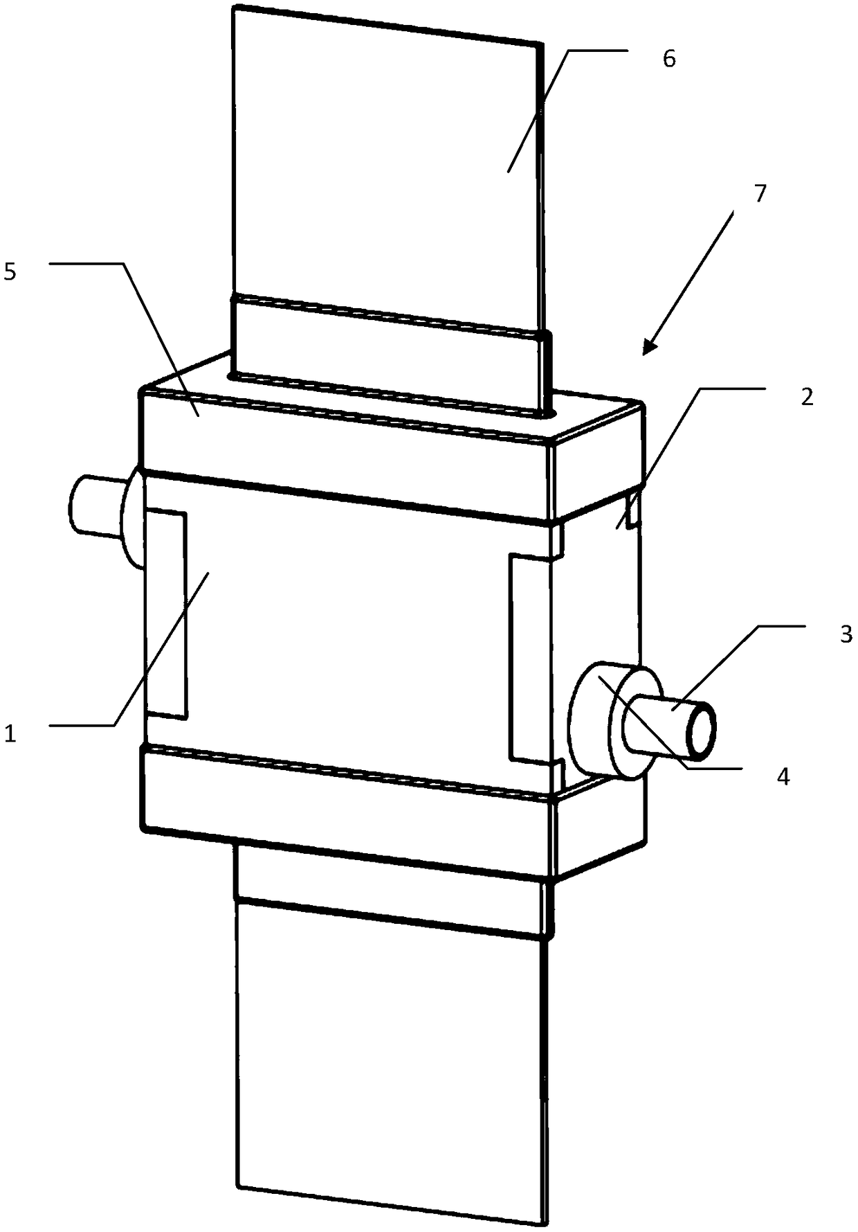
[0027] Such as figure 1 As shown, the liquid in-situ corrosion fatigue device 7 provided by the present invention includes a panel 1, a side plate 2, a conduit 3, a fixed platform 4 and a seal 5; wherein two panels 1 are arranged in parallel in the vertical direction; the two side panels 2 are respectively It is connected to the two side edges of two panels 1, thereby forming the main body of the device with a corrosion cavity formed inside; two seals 5 are respectively installed at the upper and lower ends of the main body of the device, and the middle part of each seal 5 is along the surface of the panel 1. A strip-shaped sample socket is formed in the direction; a conduit 3 is installed on each side plate 2 through a fixed table 4, the inner end of the conduit 3 passes through the side plate 2 and communicates with the corrosion cham...


PUM


Abstract

The invention provides a liquid-state in-situ corrosion fatigue device and a testing method. The device comprises a panel, a side plate, a guide pipe, a fixed platform and a sealing part. The liquid-state in-situ corrosion fatigue device has the advantages that a flow speed of a corrosion solution can be adjusted through changing the power of a submersible pump. The liquid-state in-situ corrosionfatigue device has good sealing performance, can be repeatedly utilized for long time, has certain corrosion resistance and has certain tolerance on inorganic acid and alkali type corrosion media; theliquid-state in-situ corrosion fatigue device is low in cost, simple in structure and easy to process and assemble; the testing method provided by the invention is combined, and a test sample can bemonitored in real time in a liquid in-situ corrosion fatigue experiment process. The testing method can be used for eliminating influences, caused by the corrosion solution, on DIC (Density IndicatingController) information acquisition quality; good analysis precision can be ensured. The testing method is simple in steps and is easy to operate.

Description

technical field [0001] The invention belongs to the technical field of material in-situ corrosion fatigue research, in particular to a liquid in-situ corrosion fatigue device and a testing method. Background technique [0002] In practical engineering applications, fatigue and corrosion of materials often occur at the same time. This form of failure is called corrosion fatigue, which leads to cracking of materials at low stress levels. This form of damage has no symptoms and is more likely to cause serious safety hazards. In order to study this kind of actual damage condition, it is necessary to provide a corrosion environment for the sample by the in-situ corrosion device while bearing the fatigue load, and maintain a good seal for a long time under the dynamic load to avoid the leakage of the corrosive medium, which is of great importance The in-situ corrosion device puts forward higher design requirements. At present, there are few design methods of corrosion equipment, ...

Claims


Application Information

Patent Timeline
IPC IPC(8): G01N17/00
CPCG01N17/00
Inventor 陈亚军宋先捷季春明宋肖肖王付胜
Owner CIVIL AVIATION UNIV OF CHINA
Why Eureka
Eureka Blog
Learn More