

Cup holder
a technology for cups and cups, applied in vehicle parts, transportation and packaging, vehicle arrangements, etc., can solve the problem of low flexibility in the vertical positional setting of the tray, and achieve the effect of high flexibility in the vertical positional setting
- Summary
- Abstract
- Description
- Claims
- Application Information
AI Technical Summary
Benefits of technology
Problems solved by technology
Method used
Image

Examples
first embodiment
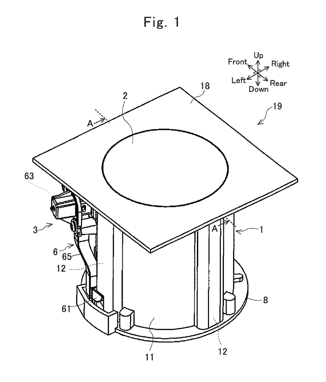
[0043]A cup holder according to the present embodiment is mounted at a center console in the interior of a vehicle. The drawings depicting the cup holder according to the present embodiment indicate front, rear, right, left, up, and down directions viewed from a driver on a driver's seat of the vehicle.
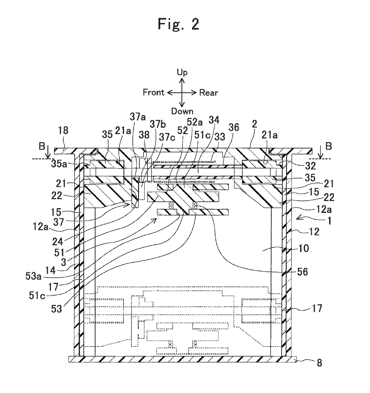
[0044]As depicted in FIGS. 1 and 2, the cup holder according to the present embodiment includes a holder body 1, a tray 2, and a height adjuster 3 configured to adjust height of the tray 2.
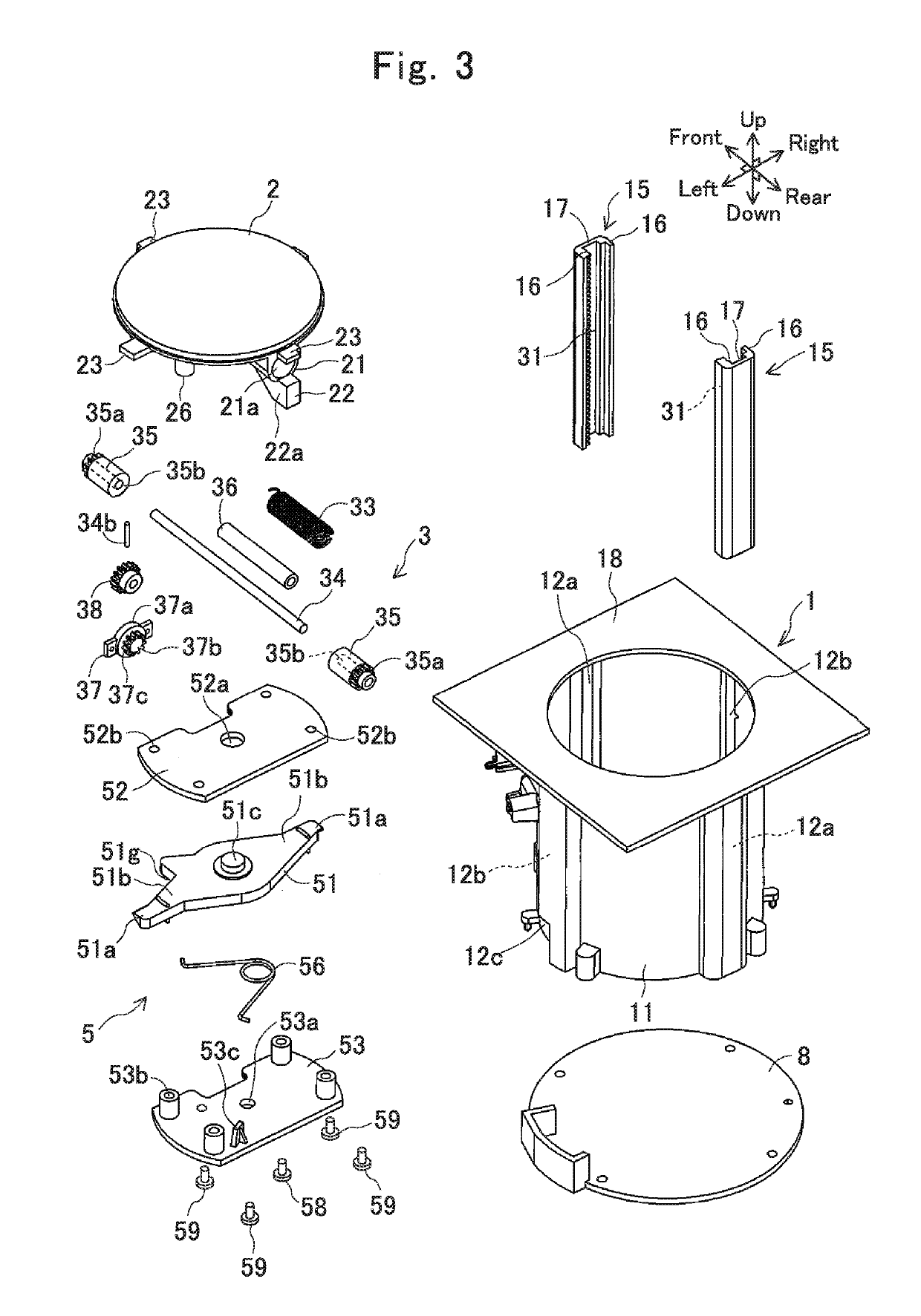
[0045]As depicted in FIG. 3, the holder body 1 includes a tubular peripheral wall 11 and an upper wall 18 expanding around the upper edge of the peripheral wall 11.
[0046]As depicted in FIG. 4, the peripheral wall 11 has four grooves 12, 12, 12, and 12 disposed at equal peripheral intervals. The four grooves 12, 12, 12, and 12 are located at front, rear, right, and left positions of a cup holder 19. Among the grooves 12 according to the present embodiment, the pair of grooves 12 and 12 disposed at th...
second embodiment
[0088]As depicted in FIG. 11, a cup holder 19 according to the present embodiment is different from the cup holder according to the first embodiment including the peripheral wall 11 provided with the four grooves 12, in that a peripheral wall 11 of a holder body 1 has two grooves 12. Furthermore, the two grooves 12 in the present embodiment accommodate pinion gears 35a provided at a tray 2 and latch portions 51a of a lock member 51.
[0089]As depicted in FIG. 12, the cup holder 19 according to the present embodiment includes a transmitting shaft 34 fixing a pair of gear members 35 having the pinion gears 35a, and the lock member 51, as in the first embodiment. As depicted in FIG. 11, the transmitting shaft 34 and the lock member 51 are disposed below the tray 2 to be in parallel with each other.
[0090]As depicted in FIG. 13, each of the pair of grooves 12 has a relatively narrow opening 12d provided in the inner peripheral surface of the peripheral wall 11. As depicted in FIG. 14, the ...
third embodiment
[0102]As depicted in FIGS. 18 and 19, the present embodiment is different from the first embodiment in that a cup holder 19 is provided with a movable wall 71 openably covering grooves 12 of a holder body 1 and includes neither the lock member 51 nor the operating part 6 of the first embodiment.
[0103]As depicted in FIG. 20, the holder body 1 includes the pair of grooves 12 and 12 provided at opposite front and rear positions, a semitubular fixed wall 11a provided on the left of the pair of grooves 12 and 12, a rectangular accommodation wall 11b provided on the right of the pair of grooves 12 and 12, and a space 100 surrounded with the fixed wall 11a and the accommodation wall 11b. The space 100 is provided, at the peripheral edge of an upper opening, with a decorative panel 18a. The decorative panel 18a has a hole 18b sized identically to an accommodation space 10 accommodating a beverage container. The decorative panel 18a is fixed integrally to an upper wall 18 by a ring member 18...
PUM
 Abstract
Description
Claims
Application Information