

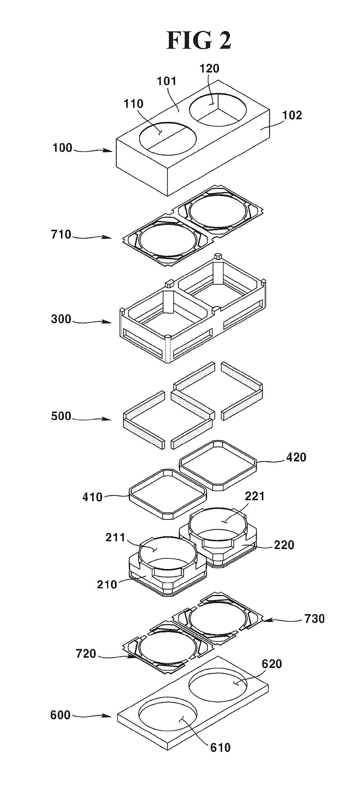
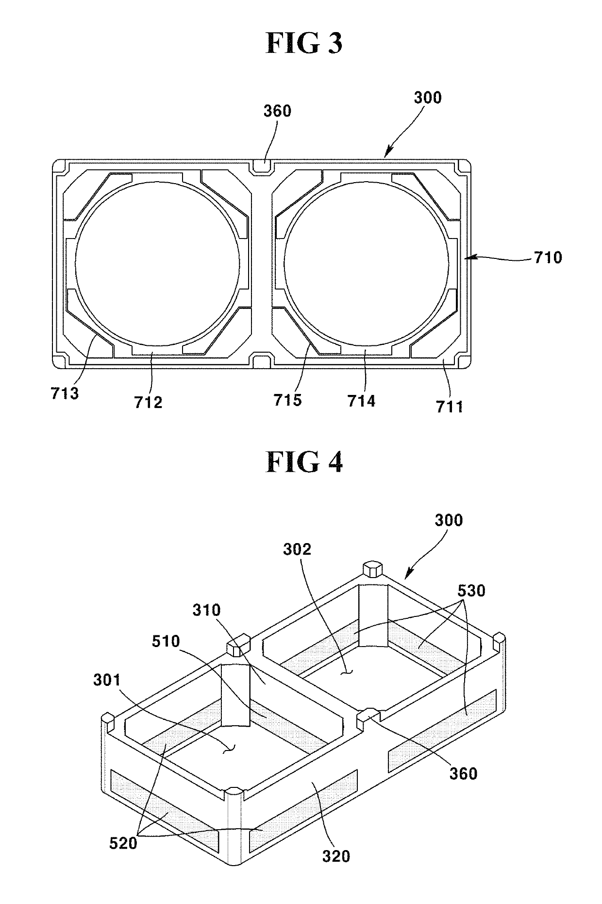
Dual camera module and optical device comprising a magnet disposed between two coils
a technology of optical device and lens driving device, which is applied in the direction of camera focusing arrangement, printers, instruments, etc., can solve the problems of long manufacturing time consumed, increased parts cost, and conventional camera modules, so as to reduce manufacturing costs and manufacturing losses, reduce manufacturing personnel, reduce manufacturing costs and defects, and reduce manufacturing costs
- Summary
- Abstract
- Description
- Claims
- Application Information
AI Technical Summary
Benefits of technology
Problems solved by technology
Method used
Image


Examples
Embodiment Construction
Technical Subject
[0006]A first exemplary embodiment of the present invention is to provide a dual camera module configured to reduce a parts manufacturing cost and a manufacturing loss. Furthermore, the first exemplary embodiment of the present invention is to provide an optical device including a dual camera module.
[0007]A second exemplary embodiment of the present invention is to provide a lens driving apparatus configured to fix an elastic member using a force coupling a magnet to a housing. Furthermore, the second exemplary embodiment of the present invention is to provide a lens driving apparatus applied with a foreign object reinforcement structure for prevention of penetration of foreign objects into a housing. Still furthermore, an exemplary embodiment of the present invention is to provide a camera module including a lens driving apparatus and an optical device.
Technical Solution
[0008]In one general aspect of the present invention, there is provided a dual camera module, co...
PUM
 Abstract
Description
Claims
Application Information