
Surgical fastener applying apparatus

a technology of fastener and application apparatus, which is applied in the field of surgical fastener application apparatus, can solve the problems of obstructed lockout structure, increased surgical procedure cost, and complex apparatus,

Active Publication Date: 2019-12-24
TYCO HEALTHCARE GRP LP
View PDF1436 Cites 670 Cited by
  • Summary
  • Abstract
  • Description
  • Claims
  • Application Information

AI Technical Summary

Benefits of technology

The patent text describes a surgical fastener applying apparatus which includes an anvil half-section, a cartridge receiving half-section, and a single use loading unit and a firing assembly mountable to the channel member. The apparatus also includes a lockout structure that prevents insertion of the single use loading unit into the channel member, if the firing assembly is secured in the cartridge receiving half-section. In an embodiment, the lockout structure includes a spring-loaded knob with a retainer pin or a spring-loaded button mounted on top of a knife actuating bar of the firing assembly. The technical effects of the lockout structure are improved safety and reliability in the use of the surgical fastener applying apparatus.

Problems solved by technology

Because of the dangers associated with improper sterilization of surgical apparatus, fastener applying apparatus are typically disposable after use.
This requirement of disposability may increase the costs associated with surgical procedures.
Although reusable fastener applying apparatus have been developed, such apparatus can be overly complex and prove difficult to sterilize.
However, the lockout structure is obstructed from moving from the first position to the second position when the firing assembly is supported within the channel member.
However, the lockout structure is obstructed from moving from the second position to the first position when the firing assembly is engaged with the single use loading unit.

Method used


Image

  • Surgical fastener applying apparatus
  • Surgical fastener applying apparatus
  • Surgical fastener applying apparatus

Examples


Embodiment Construction

[0083]Embodiments of the presently disclosed surgical fastener applying apparatus in accordance with the present disclosure will now be described in detail with reference to the drawings wherein like reference numerals identify similar or identical structural elements. As used herein, as is traditional, the term “proximal” refers to the part of the apparatus which is closer to the user and the term distal refers to the part of the apparatus which is further away from the user.

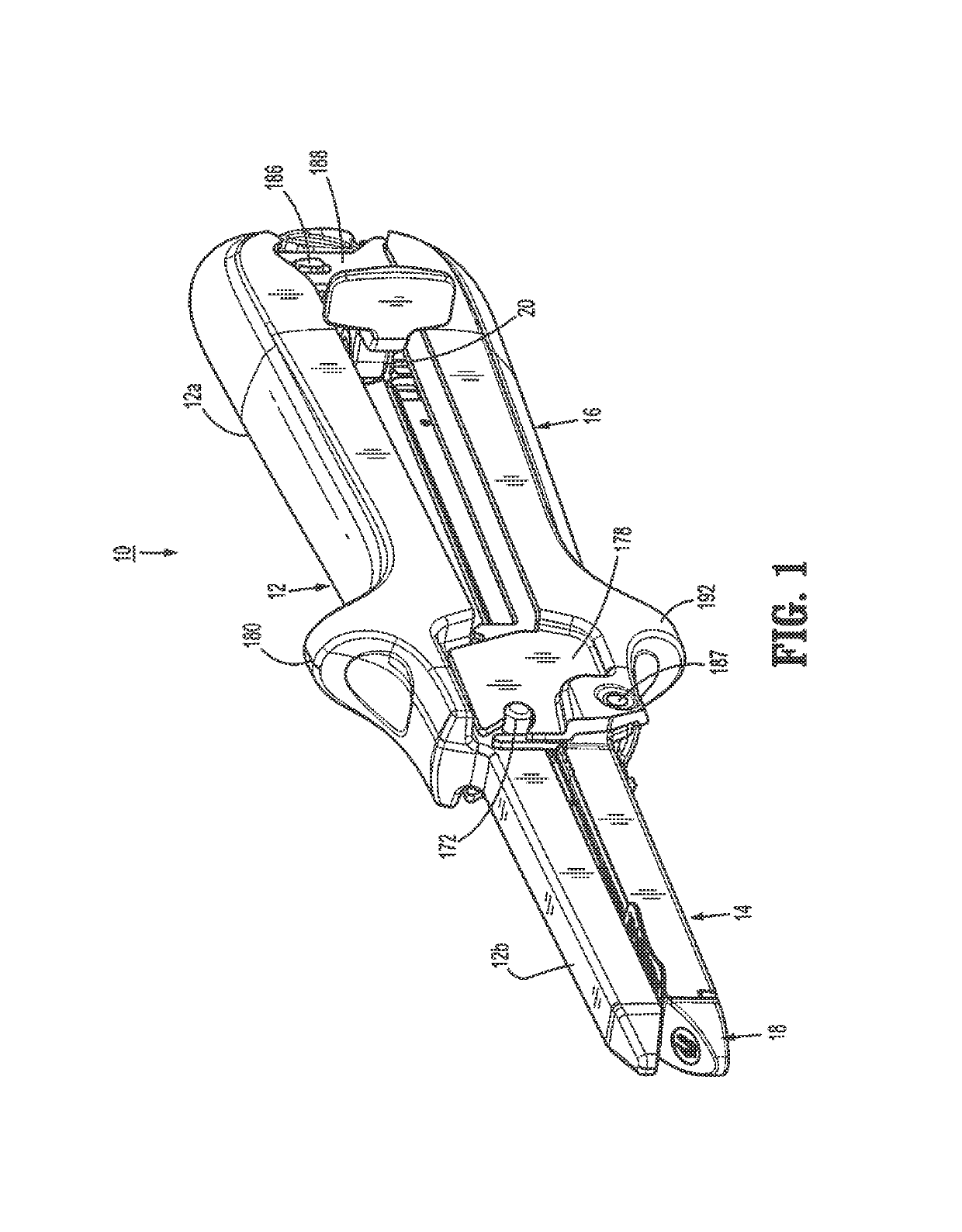
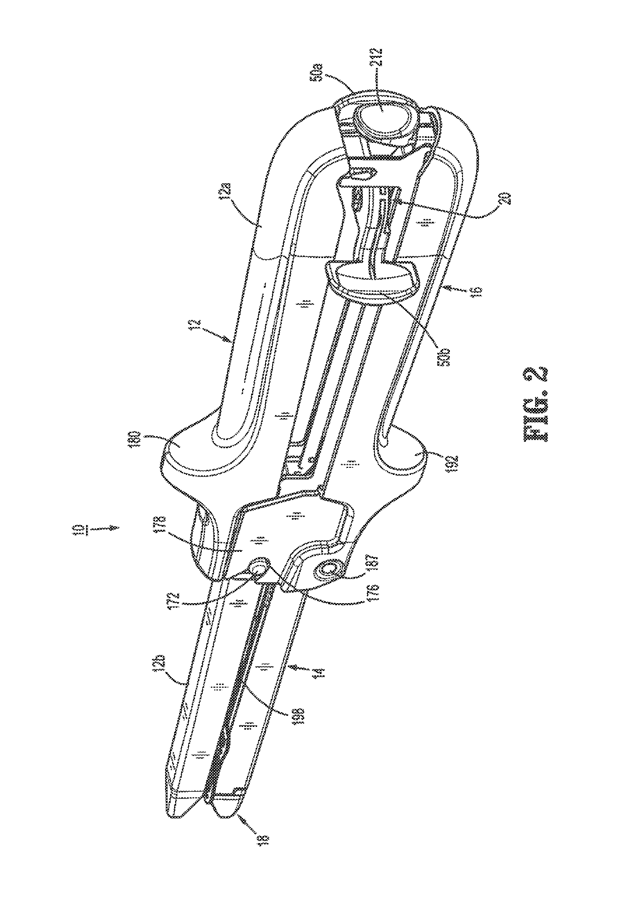
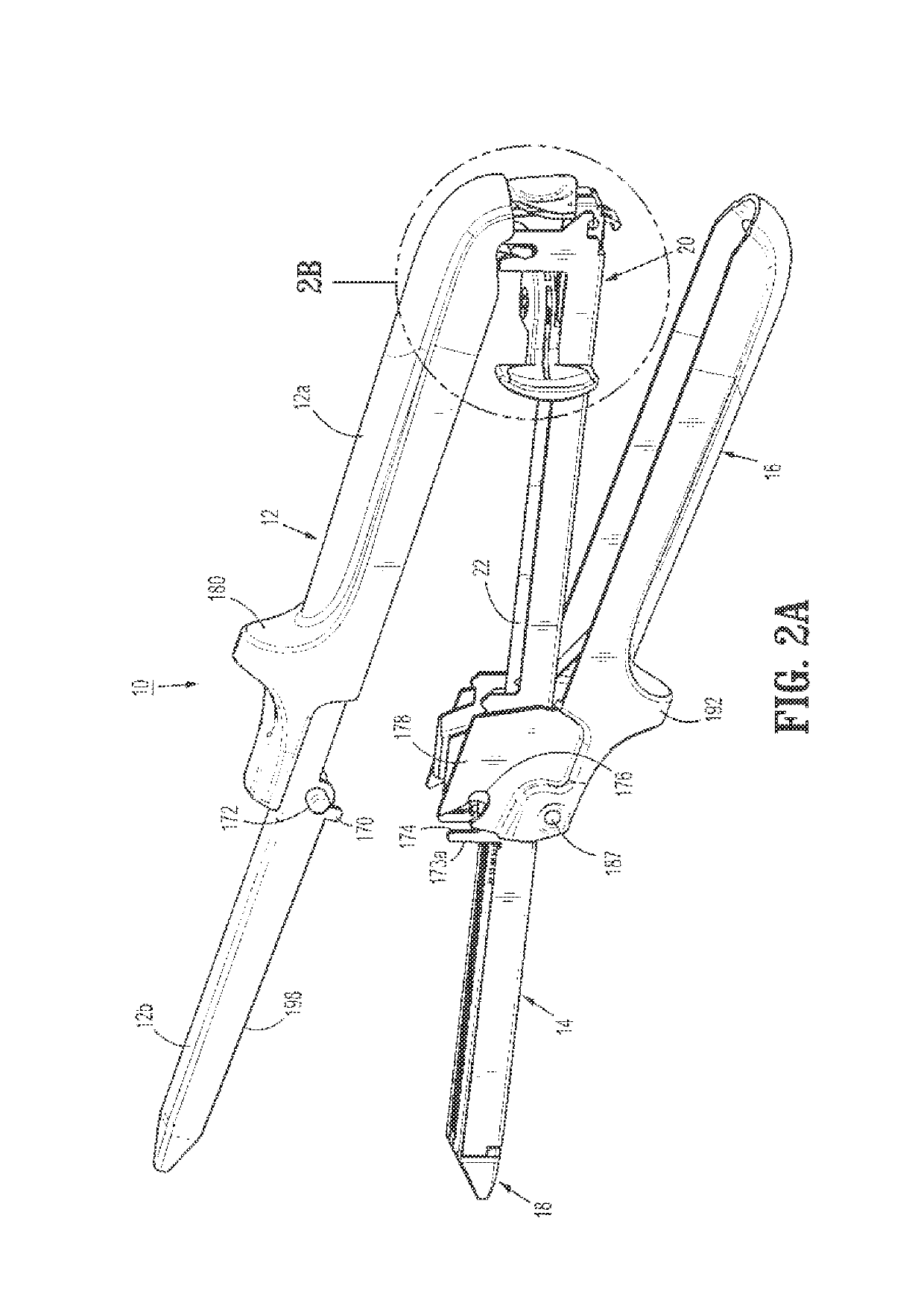
[0084]Referring to FIGS. 1-3, surgical stapler 10 includes an anvil half-section 12, a cartridge receiving half-section 14, a clamping lever 16, a single use loading unit 18 (hereinafter “SULU”) and a firing assembly 20. In an embodiment, anvil half-section 12, cartridge receiving half-section 14 and clamping lever 16 are constructed to be reusable components and, as such, are constructed from a biocompatible material suitable for sterilization and repeated use, e.g., stainless steel. In contrast, SULU 18 and f...


PUM


Abstract

The present disclosure relates to a surgical fastener applying apparatus for applying fasteners to body tissue. The apparatus includes a cartridge receiving half-section defining an elongated channel member configured to releasably receive a firing assembly and a single use loading unit. A lockout structure prevents insertion of the single use loading unit into the channel member after the firing assembly is mounted to the cartridge receiving half-section. Alternatively, the lockout structure prevents full insertion of the firing assembly into the cartridge receiving half-section, if the single use loading unit is not engaged with the firing assembly.

Description

CROSS-REFERENCE TO RELATED APPLICATIONS[0001]This application is a National Stage Application of PCT / US2014 / 038178 under 35 USC § 371 (a), the disclosure of the above-identified application is hereby incorporated by reference in its entirety.BACKGROUND[0002]1. Technical Field[0003]The present disclosure relates to a surgical fastener applying apparatus and, more particularly, to a surgical fastener applying apparatus having reusable and disposable components.[0004]2. Discussion of Related Art[0005]Surgical fastener applying apparatus, wherein tissue is first grasped or clamped between opposing jaw structures and then joined by means of surgical fasteners, are well known in the art. In some such apparatus, a knife is provided to cut the tissue which has been joined by the fasteners. The fasteners are typically in the form of surgical staples, although, other surgical fasteners may also be utilized, such as, for example, clips or two part polymeric surgical fasteners.[0006]Surgical fa...

Claims


Application Information

Patent Timeline
Patent Type & Authority Patents(United States)
IPC IPC(8): A61B17/072A61B90/00
CPCA61B17/07207A61B2017/07257A61B2017/07278A61B2090/0813A61B2017/07271
Inventor GUPTA, ARVIND KUMARDHAKAD, HARSHOTTAM SINGHGARIKIPATI, KIRANKATRE, NIKHIL R.VIVEKANANDAN, VINAYANKAPADIA, SALMAN
Owner TYCO HEALTHCARE GRP LP
Learn More