Improvements to machining process control

a technology of machining process and control, applied in the direction of program control, electric program control, instruments, etc., can solve the problems of sudden bursts in grinding power, machining errors, and add to the overall time taken for the workpiece to be machined to its finished siz

Active Publication Date: 2019-12-24
FIVES LANDIS
View PDF13 Cites 0 Cited by
  • Summary
  • Abstract
  • Description
  • Claims
  • Application Information

AI Technical Summary

Benefits of technology

[0010]These undesirable characteristics and delays associated with existing processes are addressed by the present invention. The control arrangement (for example the control system of a CNC machine tool) demands a continually decreasing relative velocity during at least the majority of the time that the tool and workpiece are in contact. Abrupt accelerations and decelerations may be reduced or avoided. Also, the time taken to remove the grinding stock from a workpiece can be reduced by avoiding delays of the nature referred to above which are associated with existing phase-by-phase machining control.
[0013]The profile of relative velocity against time for a machining operation may be calculated to minimise the time taken to arrive at the finished component dimensions whilst keeping below the maximum material removal rate dictated by the burn threshold for a given operation.
[0024]In some embodiments, removal of material from the workpiece continues during the step of detecting at least one dimension of the portion of the workpiece. In this way, a measurement may be taken and any adjustment needed to the machining operation made without any significant increase of the time taken to execute the machining operation. The machine tool may be configured to determine and implement any required adjustment as the machining operation continues without needing to pause the material removal. In this way the machining operation may be continuous and able to be smoothly executed whilst incorporating any necessary corrections.
[0031]In a preferred embodiment, the control arrangement may determine an intervening velocity profile which provides a smooth transition between the current relative velocity profile and the new relative velocity profile. This enables any adjustment to the relative velocity to be implemented smoothly.

Problems solved by technology

This causes abrupt changes in the movement of the tool and corresponding high jerk characteristics which can lead to sudden bursts in grinding power and machining errors.
Such suspension of the feed towards size or small retractions from the workpiece can be time-consuming, adding to the overall time taken for the workpiece to be machined to its finished size.

Method used


Image

  • Improvements to machining process control
  • Improvements to machining process control
  • Improvements to machining process control

Examples


Embodiment Construction

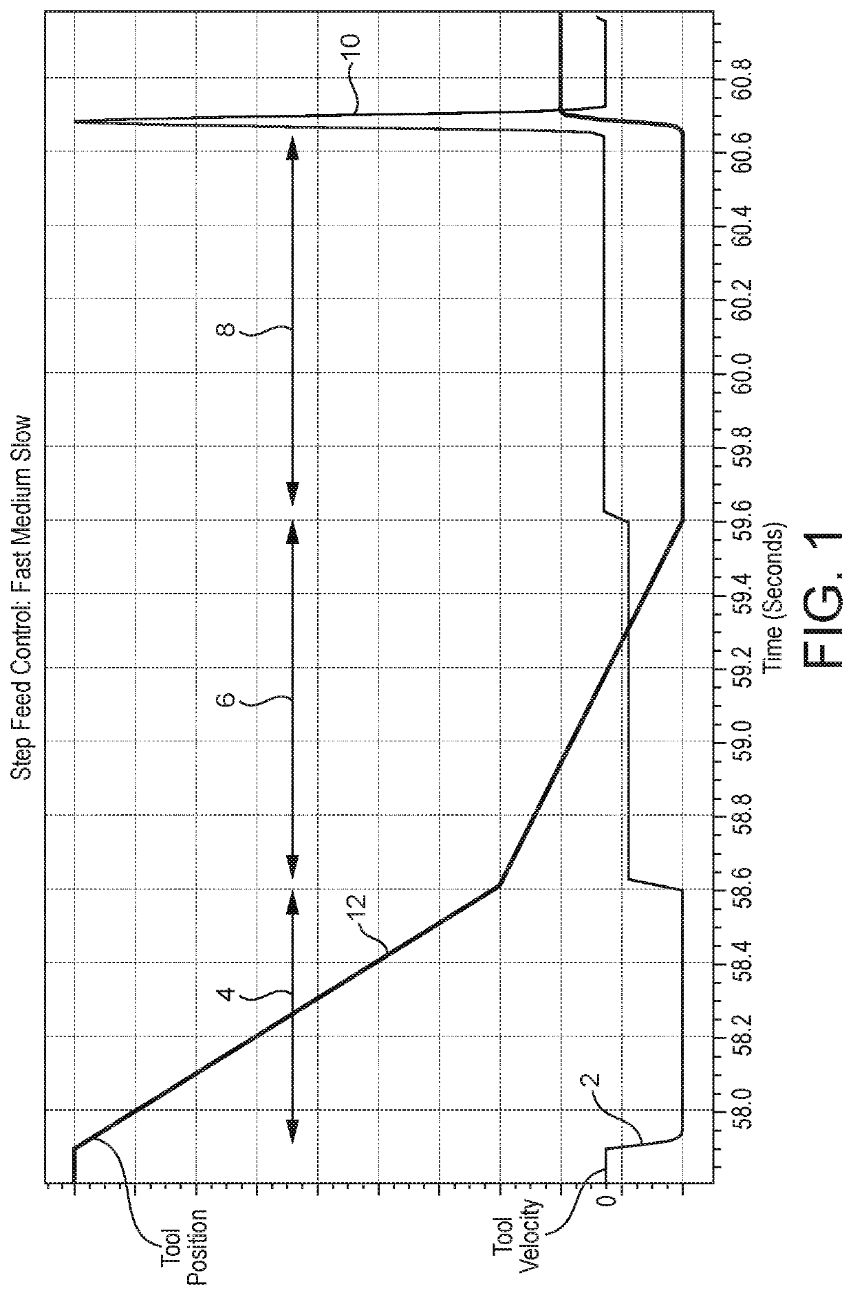
[0052]FIGS. 1 and 2 illustrate a known machining operation using phase-by-phase piecewise feed control. FIG. 1 shows a plot 2 of tool velocity relative to the is workpiece against time. It includes three distinct phases 4, 6 and 8 corresponding to “fast”, “medium” and “slow” feed rates, respectively.

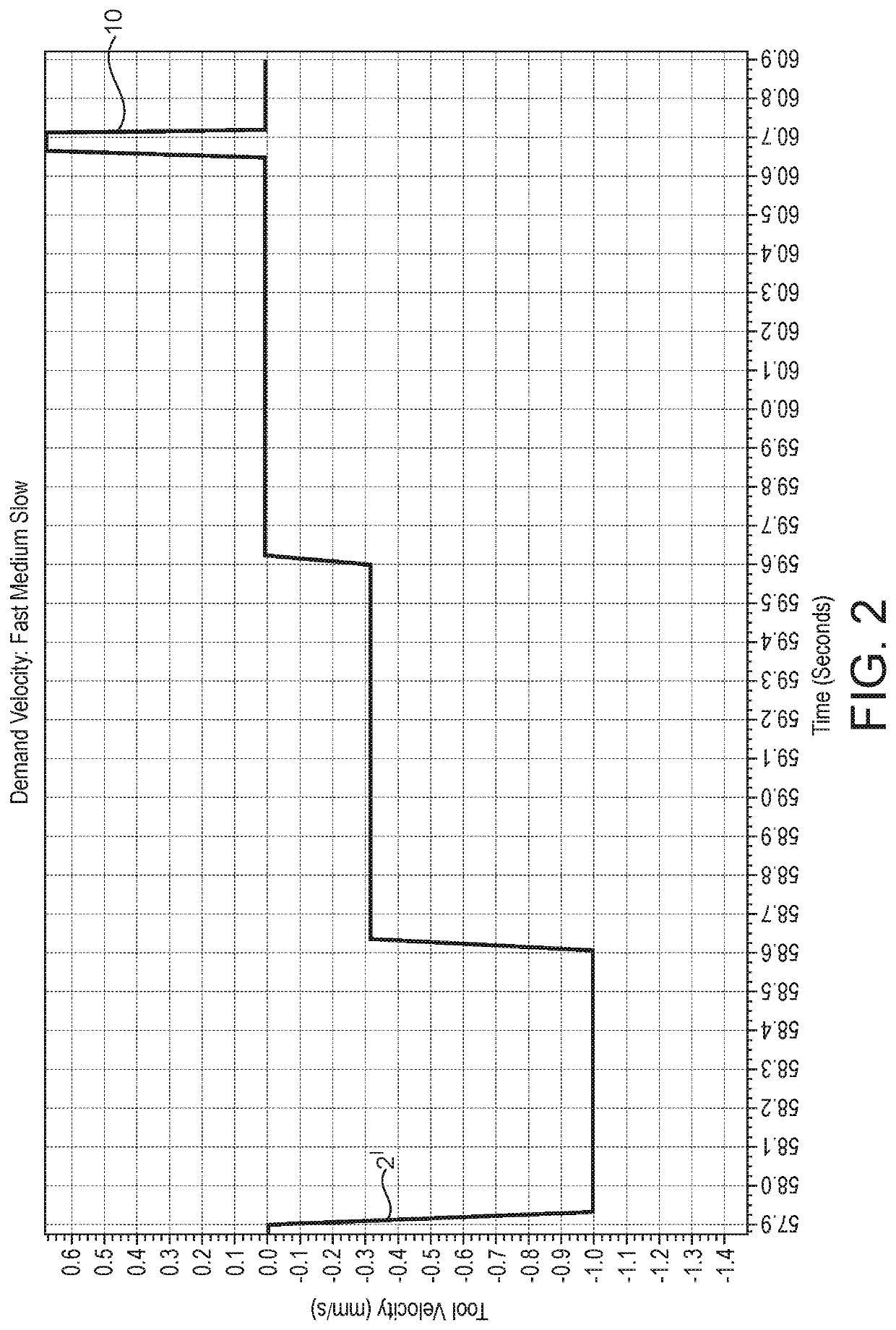
[0053]FIG. 2 shows the same machining operation in which a portion 2′ of the tool velocity plot 2 is shown with a larger scale on the vertical axis. In FIG. 2 (and other similar figures), negative values of tool velocity on the y axis represent movement towards the workpiece, with positive values representing movement away from the workpiece. Feature 10 is a spike in the plot corresponding to a short controlled retraction of the tool from the workpiece surface to avoid microscopic surface finish defects in advance of a rapid retraction and movement of the tool to the next workpiece portion to be machined. The magnitude of the tool velocity towards the workpiece during the slow feed phase...


PUM

PropertyMeasurementUnit
velocityaaaaaaaaaa
feed velocityaaaaaaaaaa

Abstract

A method of machining a workpiece using a machine tool, the machine tool comprising a tool mount carrying a tool, a workpiece mount carrying a workpiece, a drive mechanism for moving at least one of the tool mount and the workpiece mount relative to the other, and a control arrangement for controlling the drive mechanism. The method comprises moving at least one of the tool mount and the workpiece mount with the drive mechanism under the control of the control arrangement so that the tool contacts a portion of the workpiece to commence a machining operation, and the tool then removes material from the portion of the workpiece until completion of the machining operation, the movement being such that the relative velocity between the tool and the workpiece decreases continuously during the majority of the time that the tool and the workpiece are in contact with each other during the machining operation.

Description

CROSS-REFERENCE TO RELATED APPLICATION[0001]This application is a submission under 35 U.S.C. § 371 of International Application No. PCT / GB2016 / 050034, filed Jan. 8, 2016, which claims priority to Great Britain Application No. 1500259.5, filed Jan. 8, 2015 and Great Britain Application No. 1508515.2, filed May 18, 2015, the disclosures of which are hereby expressly incorporated by reference herein in their entireties.FIELD OF THE INVENTION[0002]The present invention relates to improvements in the control of machining processes carried out using a machine tool. This includes but is not limited to processes involving the use of a grinding wheel and / or a rotating workpiece.BACKGROUND OF THE INVENTION[0003]In machining processes, material is removed from a workpiece by a tool. The tool is advanced into the workpiece until it reaches a position where the workpiece is at its final finished size. For example, in abrasive or grinding machining processes, the material is removed by a large nu...

Claims


Application Information

Patent Timeline
Patent Type & Authority Patents(United States)
IPC IPC(8): B24B49/04B24B5/42B24B17/10B24B51/00G05B19/416B23Q15/10B24B1/00B23Q15/12B24B49/00
CPCB24B49/006G05B19/4163B24B49/04B24B49/045B24B51/00B24B1/007B24B5/423B24B17/10B23Q15/12B23Q15/10G05B2219/36293B24B1/00B23Q15/00B23Q15/08B24B5/42B24B49/00
Inventor GRIFFITHS, SELWYN JONATHANFALKNER, DERMOT
Owner FIVES LANDIS
Why Eureka
Try Eureka