
Improvements To Machining Process Control

a technology of process control and machining, applied in the direction of program control, electric programme control, instruments, etc., can solve the problems of sudden bursts in grinding power, machining errors, and add to the overall time taken for the workpiece to be machined to its finished siz

Active Publication Date: 2018-01-04
FIVES LANDIS
View PDF11 Cites 1 Cited by
  • Summary
  • Abstract
  • Description
  • Claims
  • Application Information

AI Technical Summary

Benefits of technology

The present invention aims to solve problems with existing machining processes such as delays and poor surface quality. It aims to create a control system for a machine tool that requires a constant speed of the tool in relation to the workpiece during engagement. This results in smoother machining with fewer sudden stops and starts. The control system also allows for faster removal of material from the workpiece by avoiding delays during the process. The patent describes a control arrangement that determines a velocity profile for the machining operation in order to minimize the time needed to reach the desired dimensions while keeping below the burn threshold. The control arrangement can also smoothly transition between different velocities during the machining process without stopping or starting the machine tool. Overall, the invention provides a more efficient and precise machining process.

Problems solved by technology

This causes abrupt changes in the movement of the tool and corresponding high jerk characteristics which can lead to sudden bursts in grinding power and machining errors.
Such suspension of the feed towards size or small retractions from the workpiece can be time-consuming, adding to the overall time taken for the workpiece to be machined to its finished size.

Method used


Image

  • Improvements To Machining Process Control
  • Improvements To Machining Process Control
  • Improvements To Machining Process Control

Examples


Embodiment Construction

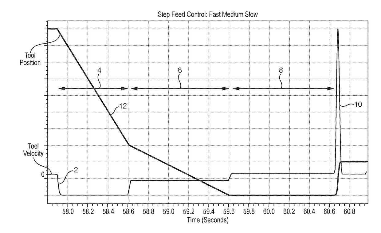
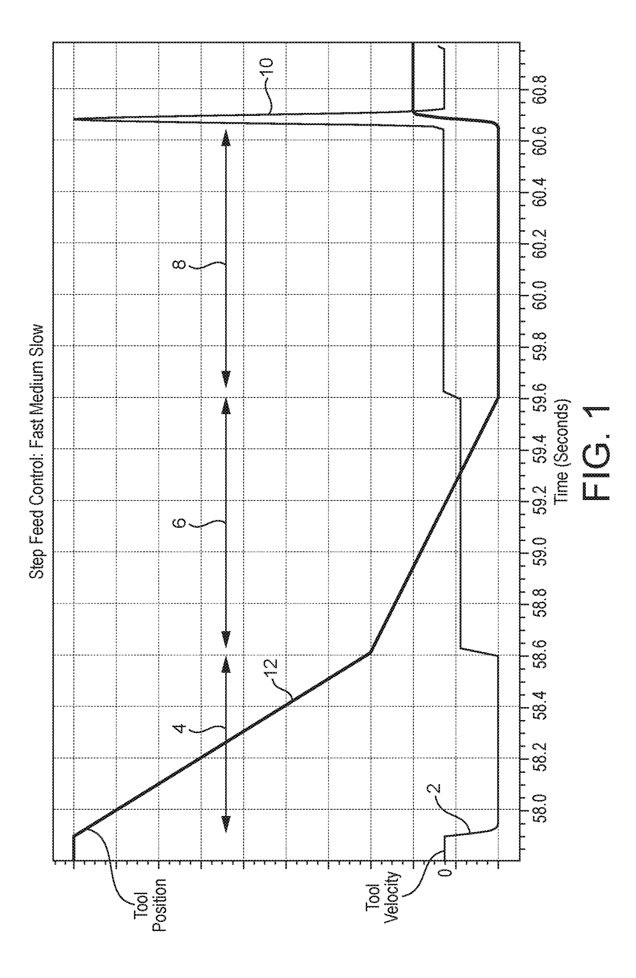
[0051]FIGS. 1 and 2 illustrate a known machining operation using phase-by-phase piecewise feed control. FIG. 1 shows a plot 2 of tool velocity relative to the is workpiece against time. It includes three distinct phases 4, 6 and 8 corresponding to “fast”, “medium” and “slow” feed rates, respectively.

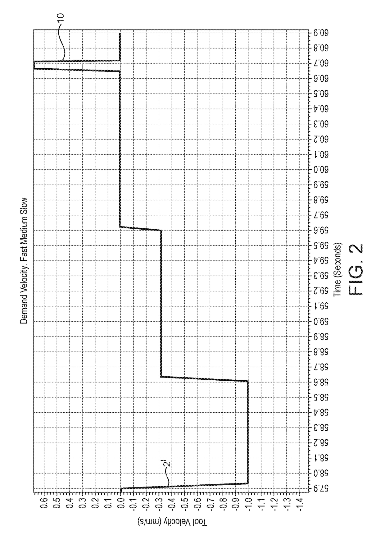
[0052]FIG. 2 shows the same machining operation in which a portion 2′ of the tool velocity plot 2 is shown with a larger scale on the vertical axis. In FIG. 2 (and other similar figures), negative values of tool velocity on the y axis represent movement towards the workpiece, with positive values representing movement away from the workpiece. Feature 10 is a spike in the plot corresponding to a short controlled retraction of the tool from the workpiece surface to avoid microscopic surface finish defects in advance of a rapid retraction and movement of the tool to the next workpiece portion to be machined. The magnitude of the tool velocity towards the workpiece during the slow feed phase...


PUM

PropertyMeasurementUnit
velocityaaaaaaaaaa
feed velocityaaaaaaaaaa

Abstract

A method of machining a workpiece using a machine tool, the machine tool comprising a tool mount carrying a tool, a workpiece mount carrying a workpiece, a drive mechanism for moving at least one of the tool mount and the workpiece mount relative to the other, and a control arrangement for controlling the drive mechanism. The method comprises moving at least one of the tool mount and the workpiece mount with the drive mechanism under the control of the control arrangement so that the tool contacts a portion of the workpiece to commence a machining operation, and the tool then removes material from the portion of the workpiece until completion of the machining operation, the movement being such that the relative velocity between the tool and the workpiece decreases continuously during the majority of the time that the tool and the workpiece are in contact with each other during the machining operation.

Description

FIELD OF THE INVENTION[0001]The present invention relates to improvements in the control of machining processes carried out using a machine tool. This includes but is not limited to processes involving the use of a grinding wheel and / or a rotating workpiece.BACKGROUND TO THE INVENTION[0002]In machining processes, material is removed from a workpiece by a tool. The tool is advanced into the workpiece until it reaches a position where the workpiece is at its final finished size. For example, in abrasive or grinding machining processes, the material is removed by a large number of cutting points held in a friable matrix which may be in the form of a grinding wheel.[0003]In existing machining processes, an operation to bring a portion of a workpiece to its final size is divided into a number of distinct, separate phases. Commonly, these phases may be denoted as “fast”, “medium” and “slow” feed operations. An example of process control in this way is illustrated in FIG. 8 of US 2014 / 0213...

Claims


Application Information

Patent Timeline
Patent Type & Authority Applications(United States)
IPC IPC(8): B24B1/00B24B5/42B23Q15/10B24B17/10B24B49/04B24B51/00G05B19/416
CPCB24B1/007B23Q15/10B24B5/423B24B17/10B24B49/045B24B51/00G05B19/4163G05B2219/36293B24B1/00B23Q15/00B23Q15/08B24B5/42B24B49/00B24B49/04B24B49/006B23Q15/12
Inventor GRIFFITHS, SELWYN JONATHANFALKNER, DERMOT
Owner FIVES LANDIS
Learn More