
Vehicular optical system

a technology of optical system and optical device, applied in the field of optical system, can solve the problems of lens and glass the anti-fogging portion disposed in front of the optical device becomes foggy, and the above-mentioned optical system cannot be properly operated, so as to improve the anti-fogging properties of the first region (angle of view)

Active Publication Date: 2019-12-24
TOYOTA JIDOSHA KK
View PDF20 Cites 0 Cited by
  • Summary
  • Abstract
  • Description
  • Claims
  • Application Information

AI Technical Summary

Benefits of technology

[0006]The disclosure provides a vehicular optical system that is capable of suppressing the possibility of the system not being operated properly by a transparent member becoming foggy with the transparent member in front of an optical device and within the angle of view of the optical device.
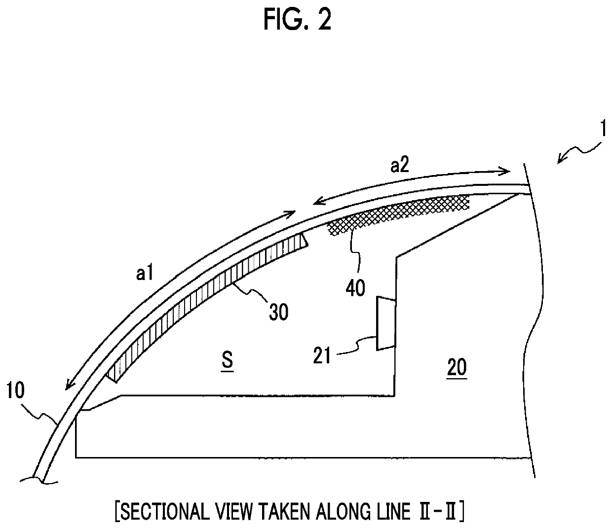
[0008]According to the aspect, dew condensation by the dew condensation portion can be preferentially performed before moisture absorption by the anti-fogging sheet, the moisture (water vapor) that is included in the closed space and causes the transparent member to become foggy is allowed to concentrate in the dew condensation portion, and thus the amount of the moisture in the anti-fogging sheet can be decreased. Accordingly, the anti-fogging sheet becomes unlikely to reach a moisture absorption limit and the anti-fogging properties of the first region (an angle of view) in front of the optical device are improved.
[0010]According to the aspect, the thermal conductivity of the transparent member can be improved more in the second region (out of the angle of view) than in the first region (angle of view) without any new configuration being added.
[0012]According to the aspect, the efficiency of heat exchange of the transparent member per coating area can be improved more in the second region (out of the angle of view) than in the first region (angle of view) without any new configuration being added.
[0014]According to the aspect, the anti-fogging properties of the first region (angle of view) can be improved in a situation in which the temperature of the air outside the vehicle cabin of the windshield and the temperature of the air inside the vehicle cabin of the windshield differ from each other.

Problems solved by technology

The vehicular optical system described above may not be operated properly when a lens and glass in front of the optical device becomes foggy due to, for example, the difference between the temperature of the air inside the vehicle and the temperature of the air outside the vehicle.
In the structures disclosed in JP 2002-350966 A, JP 11-084473 A, and JP 2008-239018 A, however, the anti-fogging portion disposed in front of the optical device becomes foggy when the anti-fogging performance of the anti-fogging portion exceeds a limit.
In other words, a transparent member such as the glass that is in front of the optical device and within the angle of view of the optical device becomes foggy when the anti-fogging performance of the anti-fogging portion exceeds a limit.
Then, the vehicular optical system may not be operated properly.

Method used


Image

  • Vehicular optical system
  • Vehicular optical system

Examples


Embodiment Construction

[0019]Overview

[0020]A vehicular optical system decreases the amount of moisture in the region of the angle of view of an optical device by allowing the moisture that is included in a closed space to concentrate in a region of the inner surface of a transparent member that is out of the angle of view of the optical device with the closed space formed by the optical device and the transparent member such as a windshield being attached to each other. As a result, the possibility of the system becoming inoperable by the transparent member on the front surface of the optical device becoming foggy can be suppressed.

[0021]Configuration of Vehicular Optical System

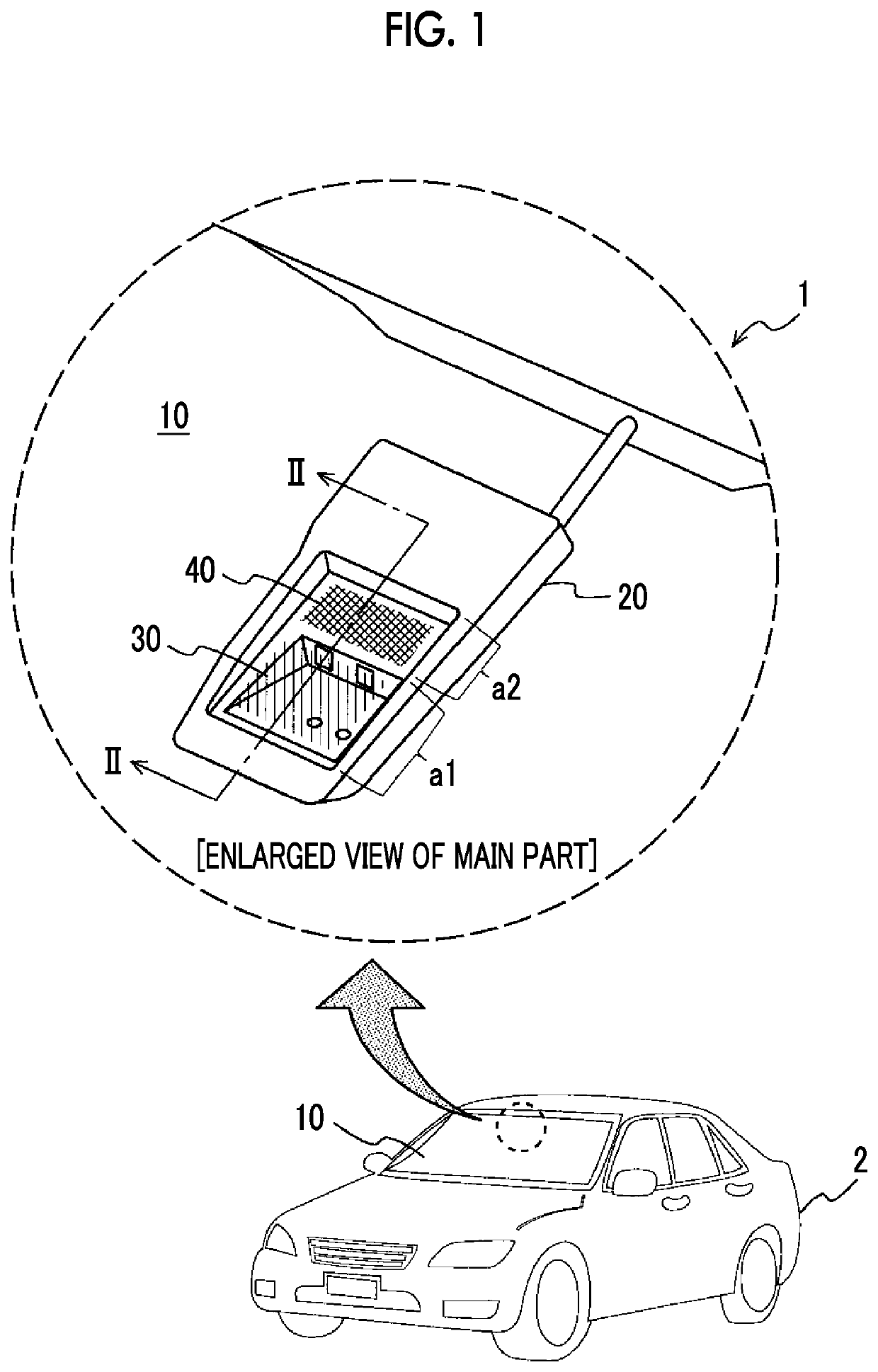
[0022]A diagram illustrating a schematic configuration of a vehicular optical system 1 according to an embodiment and an enlarged view of its main part are illustrated in FIG. 1. FIG. 2 is a sectional side view taken along line II-II of the enlarged view of the main part of the vehicular optical system 1 that is illustrated in FIG....


PUM


Abstract

A vehicular optical system includes an optical device disposed to acquire information on an environment outside a vehicle cabin, a transparent member disposed on a front surface of the optical device via a predetermined closed space, an anti-fogging sheet disposed in a first region of an inner surface of the transparent member in the closed space, the first region being within an angle of view of the optical device, and a dew condensation portion disposed in a second region of the inner surface of the transparent member in the closed space, the second region being out of the angle of view of the optical device and dew condensation being more likely to occur in the dew condensation portion than in the first region.

Description

INCORPORATION BY REFERENCE[0001]The disclosure of Japanese Patent Application No. 2017-014492 filed on Jan. 30, 2017 including the specification, drawings and abstract is incorporated herein by reference in its entirety.BACKGROUND1. Technical Field[0002]The present disclosure relates to an optical system mounted in a vehicle.2. Description of Related Art[0003]A vehicular optical system is known that acquires information on the environment in front of and behind a vehicle by using an optical device including a camera and so on and uses the information to assist in the driving of the vehicle by a driver. In most cases, the vehicular optical system is installed on the inner side of a windshield or a rear window, which is inside the vehicle cabin of the vehicle.[0004]The vehicular optical system described above may not be operated properly when a lens and glass in front of the optical device becomes foggy due to, for example, the difference between the temperature of the air inside the ...

Claims


Application Information

Patent Timeline
Patent Type & Authority Patents(United States)
IPC IPC(8): B60J1/00H04N7/18
CPCH04N7/183B60J1/002B60R1/00B60S1/56B60S1/023B60R11/04G03B17/02G03B17/08G03B17/56G03B29/00B60R2011/0026G02B7/00G03B17/00
Inventor MAETA, DAISUKEADACHI, TAKAHIROMORI, TAKEKICHIDA, KAZUMI
Owner TOYOTA JIDOSHA KK
Learn More