Gas sensor

a technology of gas sensor and lead cover, which is applied in the direction of material electrochemical variables, coupling device connections, instruments, etc., can solve the problems of air water vapor entering the lead cover, and the sealing mechanism cannot hermetically seal the lead cover, so as to reduce leakage current and enhance the accuracy of measuring gas

Active Publication Date: 2019-12-24
DENSO CORP
View PDF14 Cites 2 Cited by
  • Summary
  • Abstract
  • Description
  • Claims
  • Application Information

AI Technical Summary

Benefits of technology

[0013]It is an object of this disclosure to provide a gas sensor which is capable of minimizing the leakage current and has an enhanced accuracy in measuring gas.
[0016]The above structures of the lead-insertion-hole protrusions and the through-holes serve to minimize a risk that dew condensation water is generated in the connecting-terminal chamber of the lead cover, which causes leakage current to flow between the contact springs or the connecting terminals in the following way.
[0017]Specifically, the recess on the terminal-facing end surface occupies a gap between the adjacent the lead-insertion-hole protrusions. This prevents the dew condensation water on any of the lead-insertion-hole protrusions from expanding to the adjacent lead-insertion-hole protrusion(s). In other words, the dew condensation water on any one of the lead-insertion-hole protrusions stays thereon or is drained into the recess or the side surface of the contact-spring insulator subjecting mechanical vibration transmitted from an internal combustion engine or produced by motion of the vehicle. The draining of the dew condensation water into the recess prevents the dew condensation water from expanding over some of the lead-insertion-hole protrusions unless the recess is fully filled with the water.
[0018]The recess on the terminal-facing end surface has no through-hole formed therein, thereby avoiding simultaneous contact of droplets of the dew condensation water on the lead-insertion-hole protrusions between one of the contact springs or the connecting terminals and another of the contact springs or the connecting terminals, thereby eliminating the risk of the leakage current therebetween. This ensures the stability of the measuring operation of the gas sensor.
[0020]The inner chamber of the lead cover is made up of the connecting-terminal chamber and the contact-spring chamber which are isolated from each other by the contact-spring insulator. This prevents the dew condensation water from flowing from the connecting-terminal chamber into the contact-spring chamber even when moisture in the connecting terminal chamber enters the contact-spring chamber through gaps between the contact springs and inner walls of the through-holes.
[0021]The above structure of the gas sensor is, therefore, capable of minimizing a risk of occurrence of the leakage current and ensuring a required degree of accuracy in the gas measuring operation of the gas sensor.

Problems solved by technology

Gas sensors which are not equipped with the above type of a filter disposed on the inlet holes also have a risk that water vapor enters the lead cover.
For instance, gas sensors with no inlet hole have a sealing mechanism which blocks the entrance of the exhaust gas also face a risk that the sealing mechanism cannot hermetically seal the lead cover completely, so that the exhaust gas enters the lead cover.
Usually, electrical leads do not have a complete sealing structure and, thus, encounter a risk that air enters the lead cover.
A change in temperature of the gas sensor arising from splashing with rain, however, may cause the water vapor in the lead cover to become liquid.
Therefore, when the condensed water simultaneously touches a contact spring and a connecting terminal electrically connected to one of the electrodes and a contact spring and a connecting terminal electrically connected to the other electrode, it will cause a small amount of leakage current to flow among them, which may generate noise impinging on the output of the gas sensor.

Method used


Image

  • Gas sensor
  • Gas sensor
  • Gas sensor

Examples


Embodiment Construction

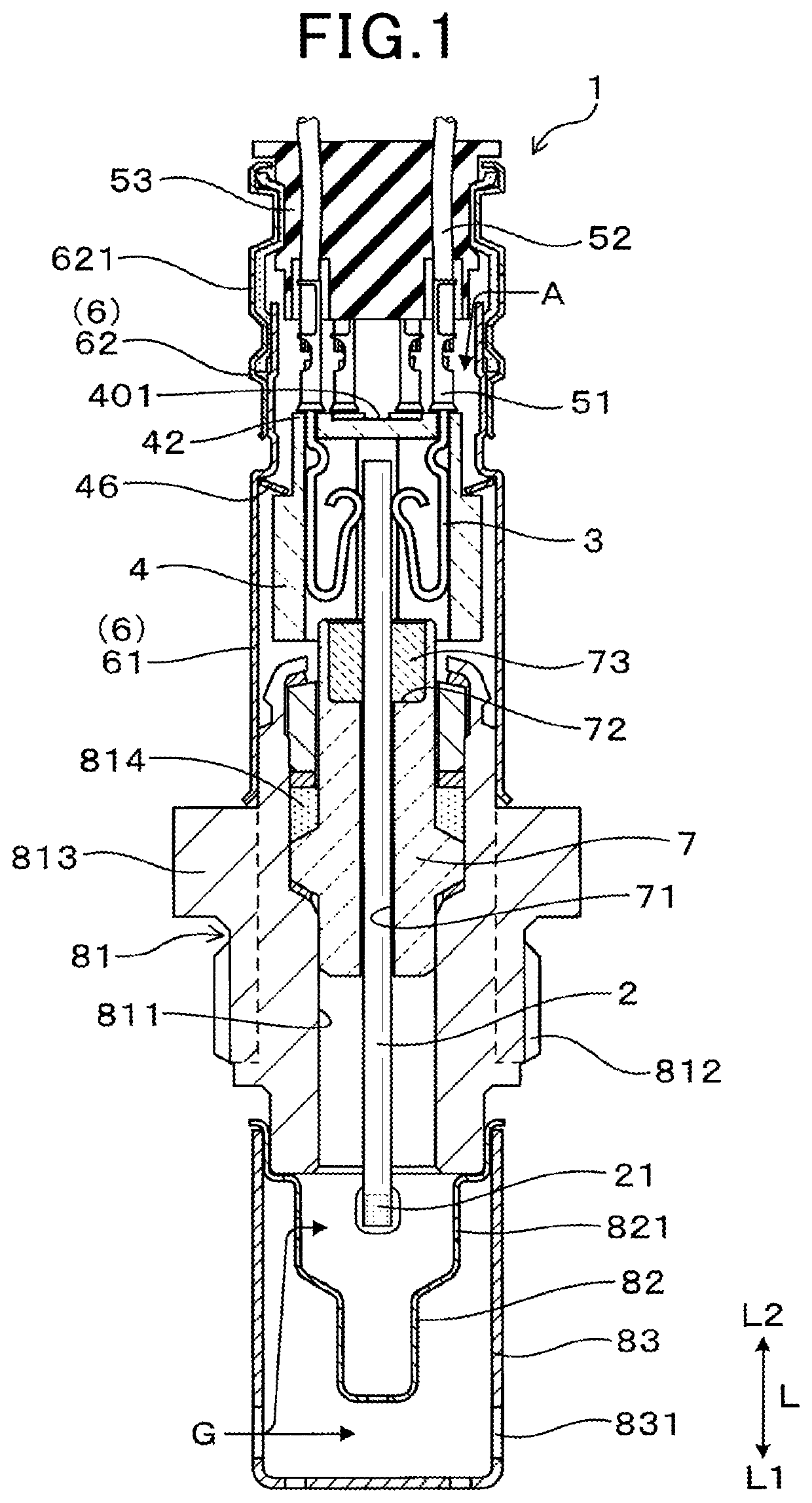
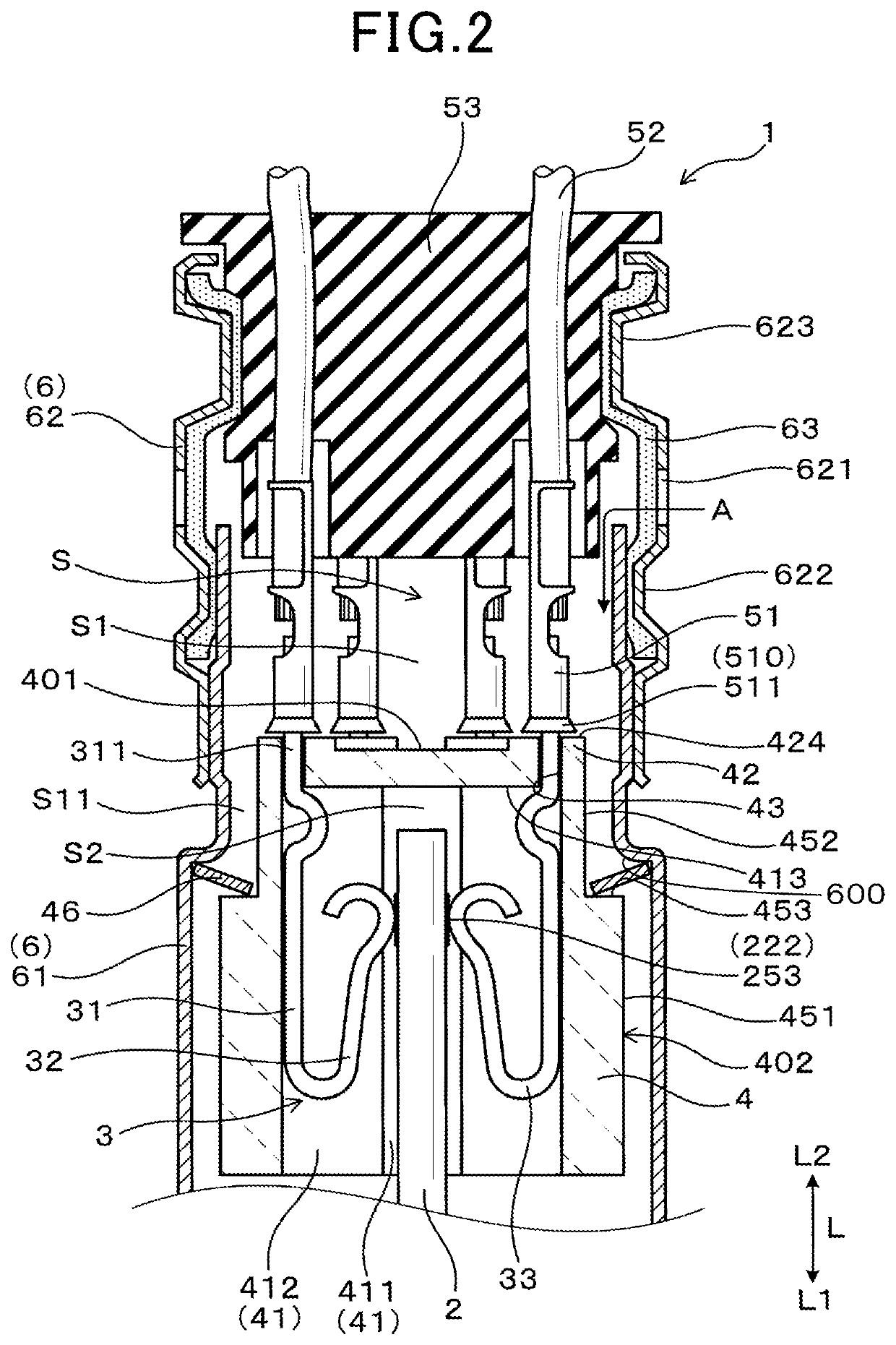
[0042]Referring now to the drawings, particularly to FIG. 1, there is shown the gas sensor 1 according to an embodiment. The gas sensor 1, as illustrated in FIG. 1, includes the sensor device 2, a plurality of contact springs 3, the contact-spring insulator 4, a plurality of connecting terminals 51, and the lead cover 6. The sensor device 2 works to measure exhaust gas G that is a target to be measured. The contact springs 3 are, as clearly illustrated in FIG. 2, placed in electrical contact with the electrode leads 222 disposed on the sensor device 2 to achieve an electrical connection of the sensor device 2 with an external control device. The contact-spring insulator 4 has formed therein the holding holes 41 in which the contact springs 3 are retained. The connecting terminals 51 are joined to electrical leads 52, respectively, which connect the contact springs 3 with the control device. The lead cover 6 covers the contact-spring insulator 4 and the connecting terminals 51.

[0043]...


PUM

PropertyMeasurementUnit
sizeaaaaaaaaaa
heightaaaaaaaaaa
heightaaaaaaaaaa

Abstract

A gas sensor is provided which includes a sensor device, a plurality of contact springs, an insulator, a plurality of connecting terminals, and a lead cover. The insulator has an end surface which faces the connecting terminals and also includes as many protrusions as the contact springs. The insulator also has formed therein holding holes in which the contact springs are disposed. Each of the protrusions has formed therein a through-hole which communicates between an end surface of the protrusion and one of the holding holes. The through-holes are discrete from each other and formed one in each of the protrusions. This minimizes a risk of occurrence of leakage current between the contact springs or the connecting terminals arising from dew condensation and ensures a high degree of measurement accuracy of the gas sensor.

Description

CROSS REFERENCE TO RELATED DOCUMENT[0001]The present application claims the benefit of priority of Japanese Patent Application No. 2016-250260 filed on Dec. 23, 2016 the disclosure of which is incorporated herein by reference.BACKGROUND[0002]1 Technical Field[0003]The invention relates generally to a gas sensor engineered to measure exhaust gas that is a target to be measured.[0004]2 Background Art[0005]Gas sensors designed to measure exhaust gas emitted from an internal combustion engine typically include a sensor device, a housing, a lead cover, a contact-spring insulator, and contact springs. The sensor device work to measure the exhaust gas. The housing retains the sensor deice using a sensor insulator. The lead cover is secured to the housing. The contact-spring insulator retains contact springs therein. The spring contacts are placed in contact with electrical leads of electrodes affixed to the sensor device and electrical leads of a heater arranged on the sensor device. The s...

Claims


Application Information

Patent Timeline
Patent Type & Authority Patents(United States)
IPC IPC(8): G01N27/407G01N27/406G01N33/00G01N27/41G01N27/409G01N27/416H01R13/508H01R13/66
CPCG01N27/4078G01N33/0027G01N27/41G01N27/409G01N27/4062G01N27/4077H01R13/6683G01N27/4074G01N27/4071H01R13/508G01N27/416G01N33/0037G01N33/0067H01R12/714H01R13/502H01R13/5221
Inventor HINO, SATOSHI
Owner DENSO CORP
Why Eureka
Try Eureka