Hitless switching when generating an output clock derived from multiple redundant input clocks

a clock generator and output clock technology, applied in the direction of generating/distributing signals, pulse automatic control, electrical equipment, etc., can solve the problems of short intervals of time, and may require switching

Active Publication Date: 2019-12-24
AURA SEMICON PVT +1
View PDF15 Cites 4 Cited by
  • Summary
  • Abstract
  • Description
  • Claims
  • Application Information

AI Technical Summary

Problems solved by technology

Such switching may be required, for example, when the earlier selected input clock fails, becomes invalid or non-functional, or when a user / operator expressly indicates to the system / device that a different input clock is to be used for deriving the output clock.
A long duration of such interval may not be desirable.

Method used


Image

  • Hitless switching when generating an output clock derived from multiple redundant input clocks
  • Hitless switching when generating an output clock derived from multiple redundant input clocks
  • Hitless switching when generating an output clock derived from multiple redundant input clocks

Examples


Embodiment Construction

1. Overview

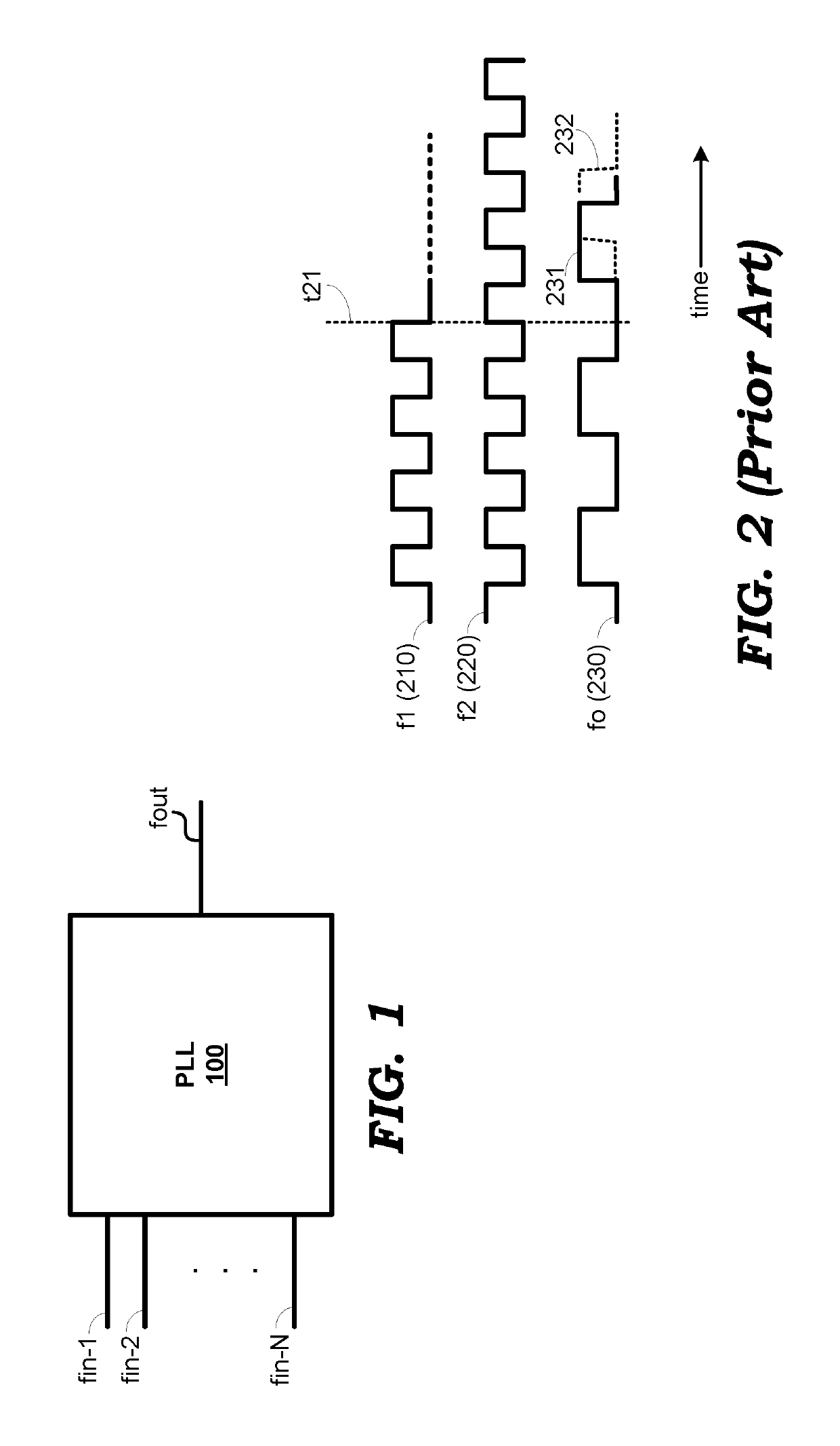
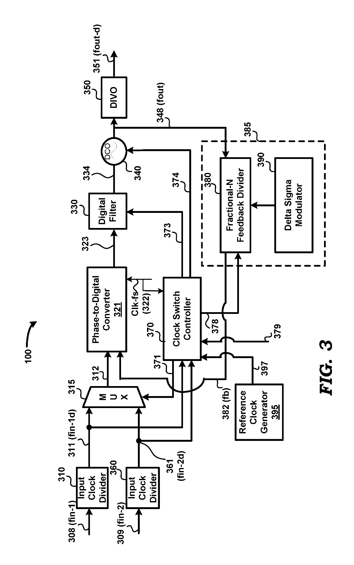
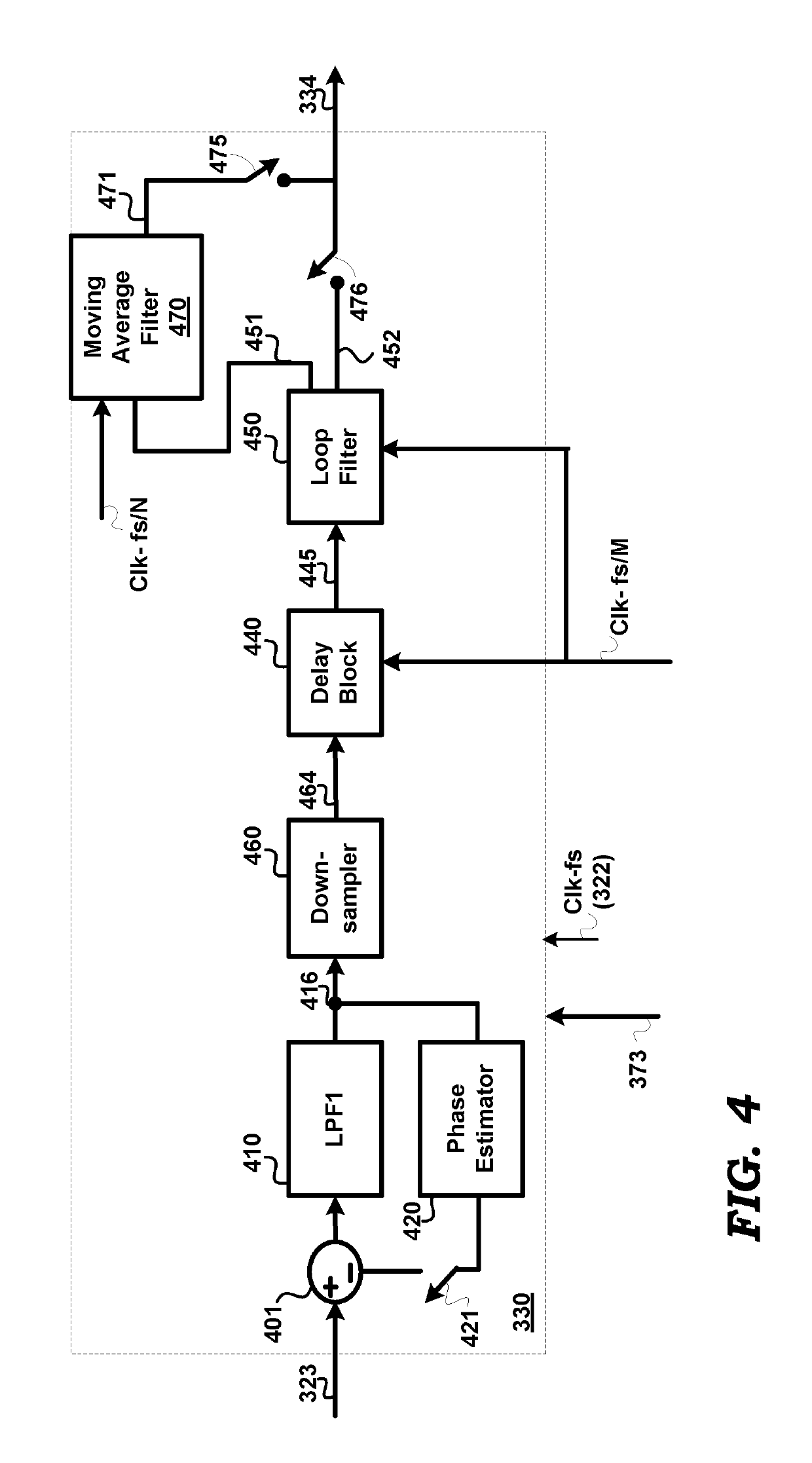
[0021]A phase locked loop (PLL) includes a multiplexer (MUX), a phase detector, a filter block, an oscillator, a frequency divider, and a clock switch controller, and achieves hitless switching between a primary clock and a redundant clock. The clock switch controller, upon detecting a condition requiring switching from the primary clock to the redundant clock, is operable to restart the feedback divider synchronously with respect to the redundant clock, and derive the output of the PLL from the redundant clock. The PLL further includes a delay block to enable the PLL to lock to, and track, delayed versions of the primary and redundant clocks.

[0022]Several aspects of the present disclosure are described below with reference to examples for illustration. However, one skilled in the relevant art will recognize that the disclosure can be practiced without one or more of the specific details or with other methods, components, materials and so forth. In other instances, well-k...


PUM


Abstract

A phase locked loop (PLL) includes a multiplexer (MUX), a phase detector, a filter block, an oscillator, a frequency divider, and a clock switch controller, and achieves hitless switching between a primary clock and a redundant clock. The clock switch controller, upon detecting a condition requiring switching from the primary clock to the redundant clock, is operable to restart the feedback divider synchronously with respect to the redundant clock, and derive the output of the PLL from the redundant clock. The PLL further includes a delay block to process delayed phase error signals generated by the phase detector. The PLL performs hitless clock switching in the event of input clock loss or in response to a command to switch input clocks. The PLL further includes circuitry for estimating and cancelling residual phase errors.

Description

PRIORITY CLAIM[0001]The instant patent application is related to and claims priority from the co-pending India patent application entitled, “HITLESS SWITCHING WHEN GENERATING AN OUTPUT CLOCK DERIVED FROM MULTIPLE REDUNDANT INPUT CLOCKS”, Serial No.: 201841022836, Filed: 19 Jun. 2018, which is incorporated in its entirety herewith to the extent not inconsistent with the disclosure herein.BACKGROUNDTechnical Field[0002]Embodiments of the present disclosure relate generally to clock generators, and more specifically to hitless switching when generating an output clock derived from multiple redundant input clocks.Related Art[0003]There are several environments in which an output clock is required to be derived from multiple redundant input clocks. Examples of such environments include telecommunication networks, for example, synchronous optical networks (SONET) and synchronous digital hierarchy (SDH).[0004]In such environments, typically, a system / device receives the multiple redundant ...

Claims


Application Information

Patent Timeline
Patent Type & Authority Patents(United States)
IPC IPC(8): G06F1/12H03L7/099H03L7/197H03L7/087
CPCG06F1/12H03L7/087H03L7/1976H03L7/0992H03L7/093
Inventor J, RAJA PRABHUSEEDHER, ANKITMARQUES, AUGUSTOSRIDHARAN, SRINATHTHAKUR, KULBHUSHAN
Owner AURA SEMICON PVT
Why Eureka
Try Eureka