
Nail hole guiding system

a guiding system and nail technology, applied in the field of orthopedic prostheses, can solve the problems of complicated process of positioning the distal hole, complicated matters, and difficulty in adjusting the position of the distal hol

Active Publication Date: 2019-12-31
BIOSENSE WEBSTER (ISRAEL) LTD
View PDF29 Cites 1 Cited by
  • Summary
  • Abstract
  • Description
  • Claims
  • Application Information

AI Technical Summary

Benefits of technology

The patent describes a method for accurately positioning a drill guide to align with the distal end hole of an nail. The jig is moved under fluoroscopy until it is in registration with the nail, and the position of the drill hole is known in relation to the magnetic generator system. The fluoroscope is then switched off, and a drill with an attached electromagnetic sensor is advanced while being monitored by the position processing system. This allows the depth of the drill to be measured by the system.

Problems solved by technology

Positioning an intramedullary nail in a long bone is a complicated process, because after positioning the nail must be locked in place.
However, the position of the distal hole is problematic, since the nail may bend when it is inserted into the bone.
However this complicates matters.

Method used


Image

  • Nail hole guiding system
  • Nail hole guiding system
  • Nail hole guiding system

Examples


Embodiment Construction

[0031]In the following description, numerous specific details are set forth in order to provide a thorough understanding of the various principles of the invention. It will be apparent to one skilled in the art, however, that not all these details are necessarily needed for practicing the invention. In this instance, well-known circuits, control logic, and the details of computer program instructions for conventional algorithms and processes have not been shown in detail in order not to obscure the general concepts unnecessarily.

[0032]Documents incorporated by reference herein are to be considered an integral part of the application except that, to the extent that any terms are defined in these incorporated documents in a manner that conflicts with definitions made explicitly or implicitly in the present specification, only the definitions in the present specification should be considered.

[0033]The terms “link”, “links”, “couple” and “couples” are intended to mean either an indirect...


PUM


Abstract

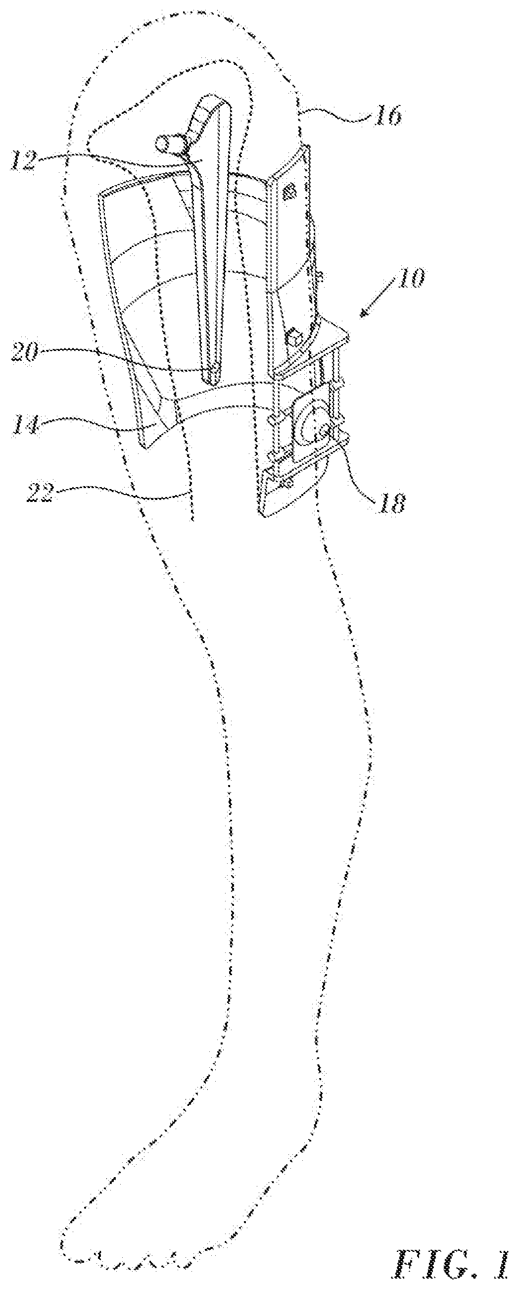
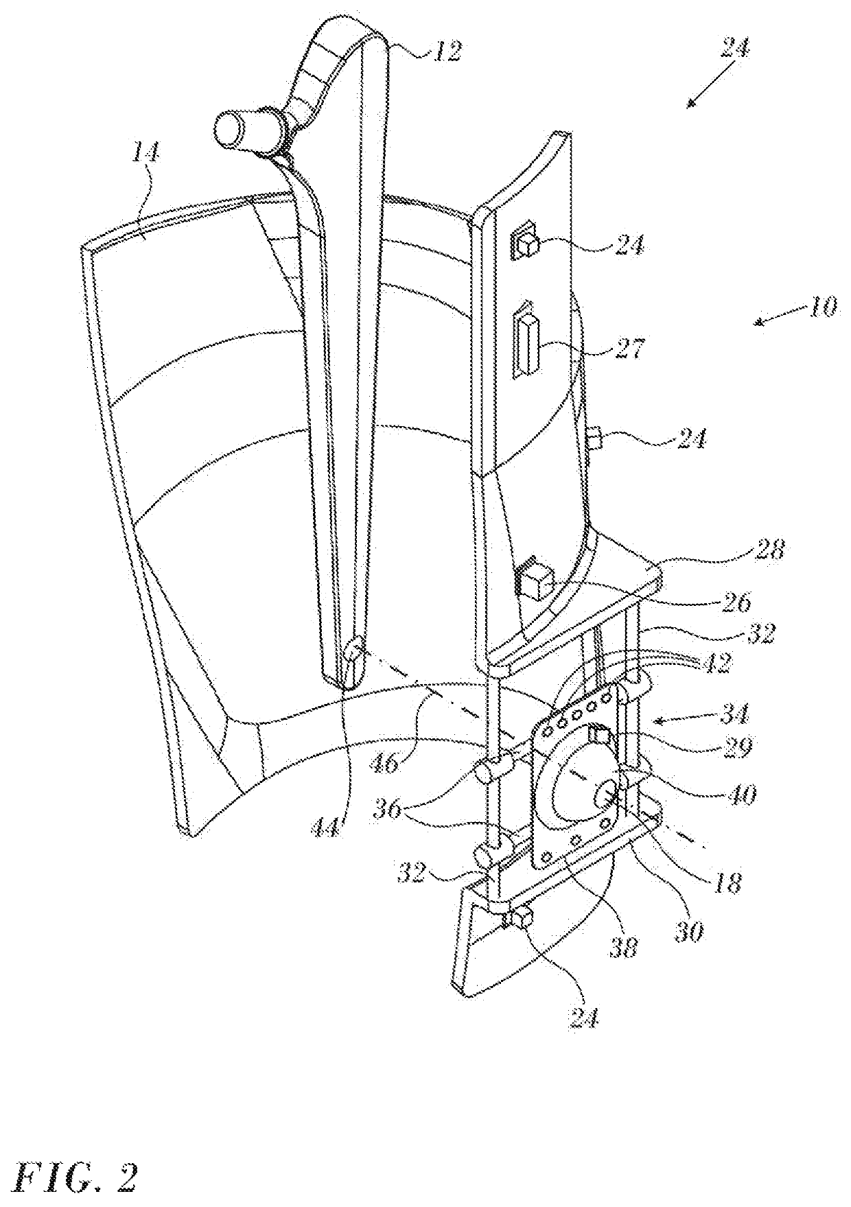
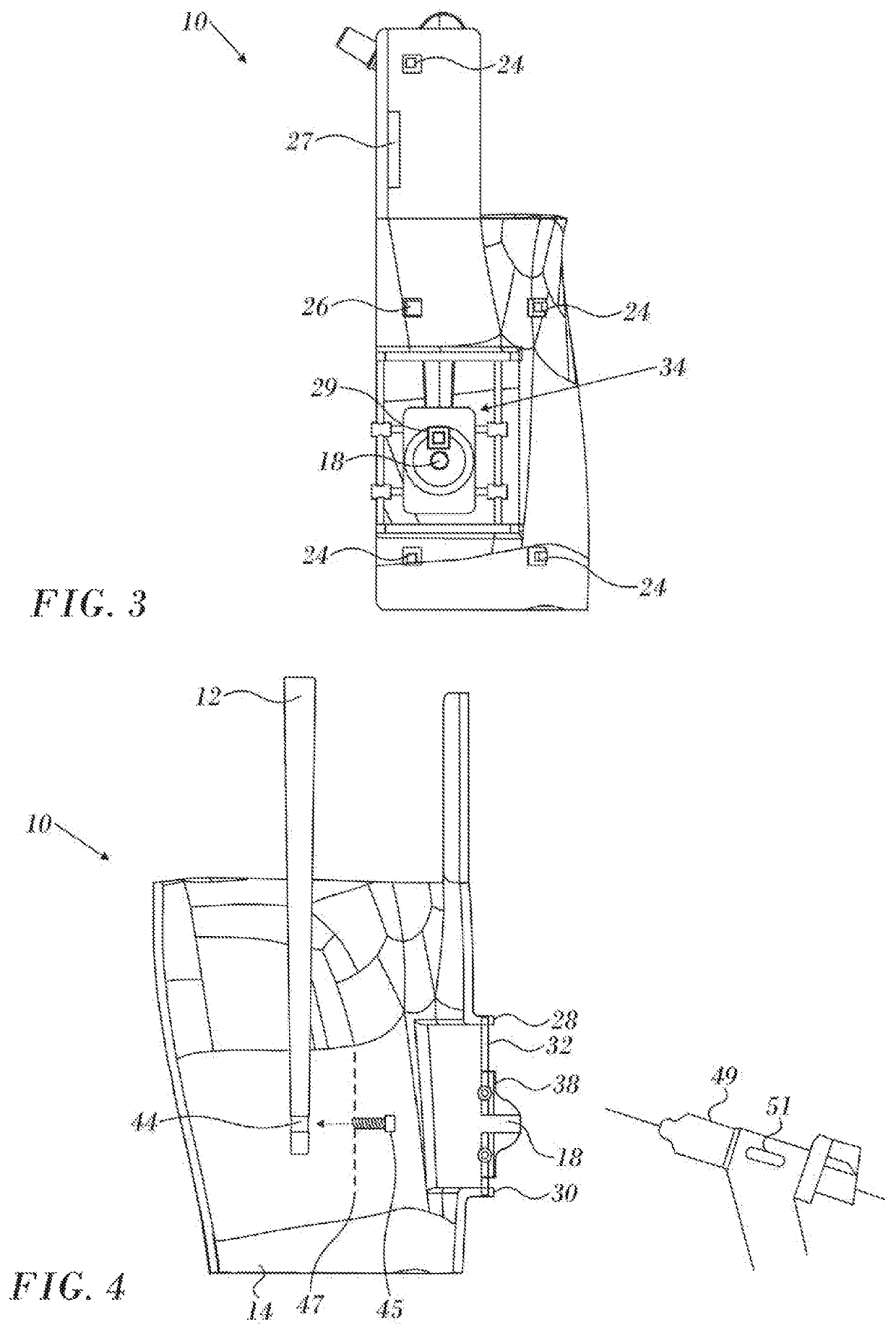
A jig for placing a screw to stabilize a femoral nail comprises a shell, a drill guide assembly movably mounted on the shell, and having a plurality of radiopaque markers affixed thereon, a magnetic field generator, and a plurality of magnetic location sensors responsive to magnetic fields produced by the magnetic field generator. A position processor is operative to compute positional information of the magnetic location sensors based on signals communicated thereto. The positional information is placed in registration with an anatomical image so that the drill guide assembly can be aligned with a transverse bore in the femoral nail.

Description

COPYRIGHT NOTICE[0001]A portion of the disclosure of this patent document contains material that is subject to copyright protection. The copyright owner has no objection to the facsimile reproduction by anyone of the patent document or the patent disclosure, as it appears in the Patent and Trademark Office patent file or records, but otherwise reserves all copyright rights whatsoever.BACKGROUND OF THE INVENTION1. Field of the Invention[0002]This invention relates to orthopedic prostheses. More particularly, this invention relates to medical instruments for implanting a medullary nail using data processing equipment.2. Description of the Related Art[0003]Positioning an intramedullary nail in a long bone is a complicated process, because after positioning the nail must be locked in place. The locking is performed by attaching screws orthogonally to the nail, at the proximal and distal ends of the nail, by drilling through the bone to holes that have been preformed in the nail. Typical...

Claims


Application Information

Patent Timeline
Patent Type & Authority Patents(United States)
IPC IPC(8): A61B17/17G05B19/402A61B34/20A61B17/00A61B90/10A61B90/98A61B90/00
CPCA61B17/1717A61B17/1725A61B17/1707A61B17/1703A61B34/20G05B19/402G05B2219/45129A61B2034/2051A61B2090/3764A61B2017/0092A61B2017/00221A61B2090/3762A61B90/98A61B2090/364A61B2090/397A61B2090/374A61B2090/376A61B2034/2072A61B90/39A61B2090/101A61B90/37A61B2090/3966A61B17/72A61B17/88A61B17/90
Inventor BAR-TAL, MEIR
Owner BIOSENSE WEBSTER (ISRAEL) LTD
Learn More