Valve for metering a fluid, especially a fuel injector

a valve and fluid technology, applied in the field of valves for metering fluids, can solve the problems that the disadvantageous effect of engine operation cannot be ruled out, and achieve the effects of preventing the rapid accumulation of soot deposits, and reducing the risk of engine failur

Active Publication Date: 2019-12-31
ROBERT BOSCH GMBH
View PDF4 Cites 0 Cited by
  • Summary
  • Abstract
  • Description
  • Claims
  • Application Information

AI Technical Summary

Benefits of technology

[0009]A further advantage of the present invention is that less sooty carbon deposit develops on the outer side of the dome-like center area during engine operation than in the case of understood fuel injectors. Due to the configuration of the valve-seat member according to the present invention, a temperature distribution which prevents the rapid buildup of soot deposits is achieved in the component.
[0010]Because of the small deposit formation on the surface of the valve-seat member, the configuration of the present invention offers greater protection against blockage of the injection openings (“coking”). In view of the highly fluctuating quality of fuel worldwide, this robust behavior is a great advantage.
[0011]A further advantage is that the increase in particulate emissions in the exhaust gas caused by the continuous operation of the engine turns out to be less than in the case of fuel injectors according to the related art (reduction of the PN drift).
[0012]The measures delineated in the dependent claims permit advantageous further developments of and improvements to the fuel injector set forth in Claim 1.
[0013]It is especially advantageous that the geometric configuration of the valve-seat member at its lower end face facing the combustion chamber may be adapted very flexibly to desired installation conditions and demands on the engine operation.
[0014]Exemplary embodiments of the present invention are represented in simplified manner in the drawing and explained in greater detail in the following description.

Problems solved by technology

Usually upon closing of the fuel injector, the valve needle bounces with the valve-closing member on the valve-seat face, so that undesirable opening phases still follow the closing operation for a brief time.
This quantity of fuel delivered in uncontrolled manner leads to a small deviation of the injected quantity of fuel from the setpoint value, so that a disadvantageous effect in the engine operation cannot be ruled out.

Method used


Image

  • Valve for metering a fluid, especially a fuel injector
  • Valve for metering a fluid, especially a fuel injector
  • Valve for metering a fluid, especially a fuel injector

Examples


Embodiment Construction

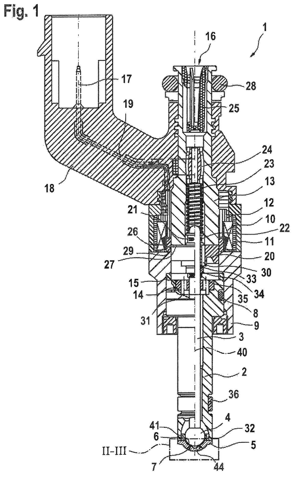
[0018]An understood example of a fuel injector 1 shown in FIG. 1 is in the form of a fuel injector 1 for fuel injection systems of mixture-compressing, spark-ignition internal combustion engines. Fuel injector 1 is particularly suited for the direct injection of fuel into a combustion chamber (not shown) of an internal combustion engine. In general, the invention is usable for valves for the metering of a fluid.

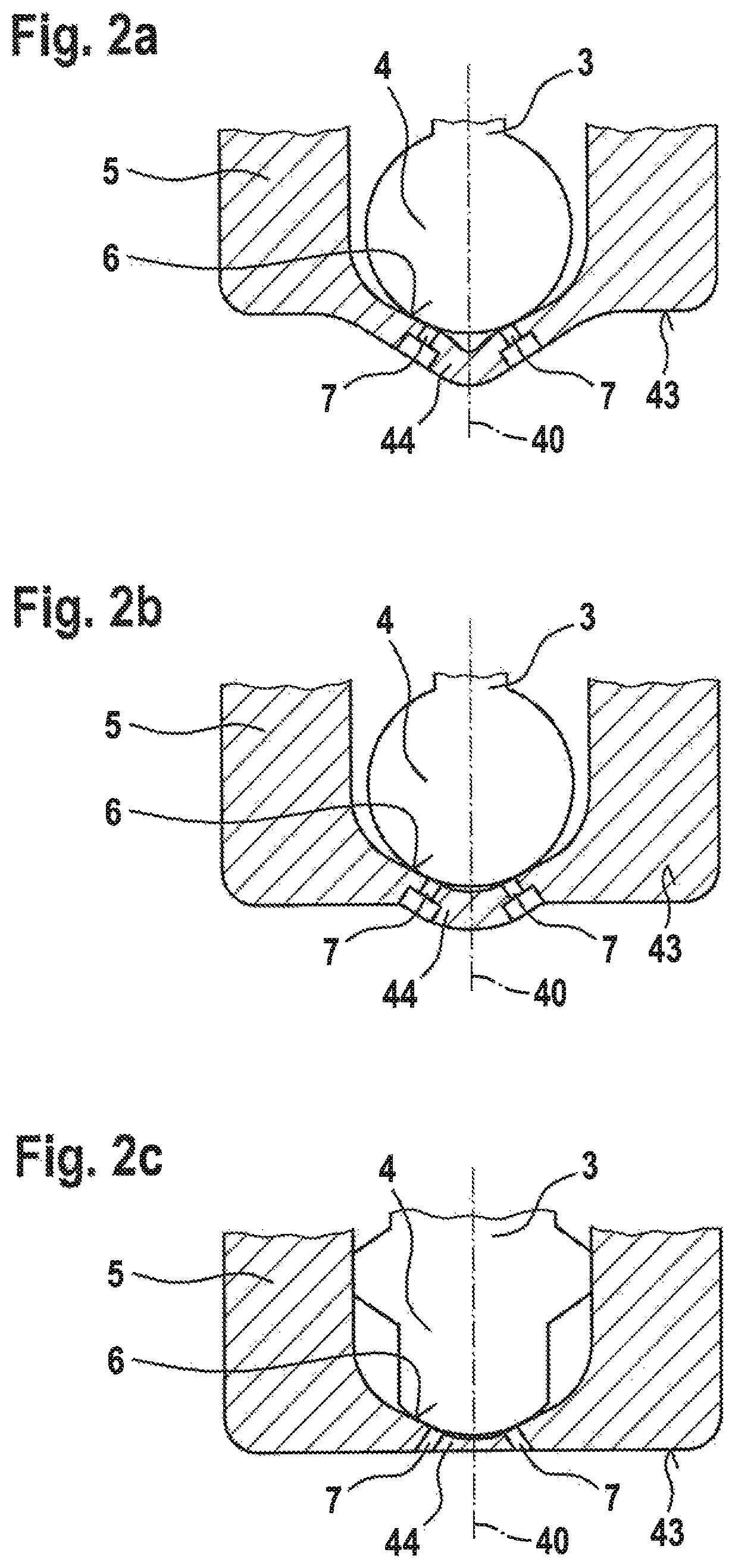
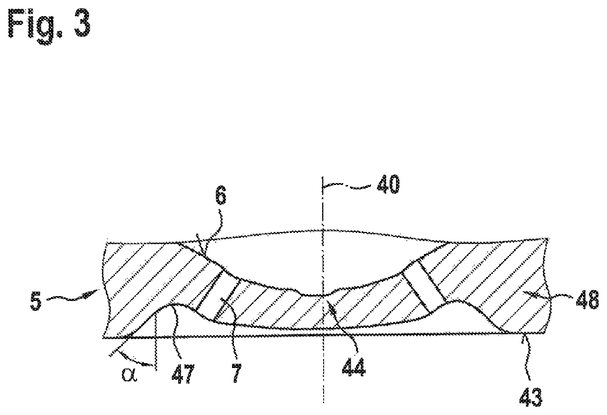
[0019]Fuel injector 1 is made up of a nozzle body 2, in which a valve needle 3 is disposed. Valve needle 3 is in operative connection with a valve-closing member 4 that interacts with a valve-seat face 6, located on a valve-seat member 5, to form a sealing seat. Valve-seat member 5 and nozzle body 2 may also be realized in one piece. Fuel injector 1 in the exemplary embodiment is an inward opening fuel injector 1 which has at least one injection opening 7, but typically has at least two injection openings 7. Ideally, however, fuel injector 1 takes the form of a multipole inje...


PUM


Abstract

A valve (or fuel injector), which provides that the valve-seat member exhibits high structural strength and fatigue strength under vibratory stresses, includes an excitable actuator for actuating a valve-closing member which, with a valve-seat face on the valve-seat member, forms a sealing seat, and injection openings which are downstream of the valve-seat face, the injection openings being in a center area of the valve-seat member projecting outwardly dome-like in the injection direction. The dome-like center area has a curved outer contour, the curvature in a radially inner section having a larger radius than the radius of the curvature in a radially outer section of the dome, which ends radially outside the mouth areas of all injection openings, in a recessed depression, that is followed radially outwardly by an axially projecting edge area of the valve-seat member. The fuel injector directly injects fuel into a combustion chamber of an engine.

Description

RELATED APPLICATION INFORMATION[0001]The present application claims priority to and the benefit of German patent application no. 10 2017 218 224.5, which was filed in Germany on Oct. 12, 2017, the disclosure of which is incorporated herein by reference.FIELD OF THE INVENTION[0002]The present invention is based on a valve for metering a fluid, especially a fuel injector.BACKGROUND INFORMATION[0003]FIGS. 1, 2a, 2b and 2c show specific embodiments of understood valve-seat members. FIGS. 2a, 2b and 2c show schematic representations of three typical basic constructions of valve-seat members having injection openings. While in the case of the configuration approach according to FIG. 2c, the valve-seat member having a flat and even end face closes the downstream valve end of the fuel injector toward the combustion chamber, in the case of the likewise configuration approaches according to FIGS. 2a and 2b, the valve-seat members are formed with a center area of the valve-seat member that pro...

Claims


Application Information

Patent Timeline
Patent Type & Authority Patents(United States)
IPC IPC(8): F02M51/06F02M61/12F02M61/18
CPCF02M61/188F02M51/066F02M61/12F02M51/0614F02M51/0685F02M61/1833F02M61/1886F02M2200/306F02M2200/8046F02M2200/8084F02M2200/9015
Inventor SOERENSEN, JENSOPFER, LARSKECK, PETER
Owner ROBERT BOSCH GMBH
Why Eureka
Try Eureka