Movable spring plate and relay thereof

a spring plate and moving technology, applied in the field of relays, can solve the problems of severe damage, interference with the connector, damage to the relay or even the whole circuit system, etc., and achieve the effects of improving the stability of the aforementioned contact device, and extinguishing the electric ar

Active Publication Date: 2019-12-31
SONG CHUAN PRECISION
View PDF2 Cites 0 Cited by
  • Summary
  • Abstract
  • Description
  • Claims
  • Application Information

AI Technical Summary

Benefits of technology

[0006]Therefore, it is a primary objective of the present invention to provide a movable spring plate structure and its relay capable of preventing electric arcs, and improving the life and performance of the relay.
[0007]To achieve the aforementioned and other objectives, the present invention provides a movable spring plate structure applied to a relay for defining an open or closed state with respect to a fixed contact, comprising: a rigid spring plate contact portion; a soft spring plate warp portion, coupled to the rigid spring plate contact portion, and having a first deformation gap formed between the rigid spring plate contact portion and the soft spring plate warp portion, and the rigid spring plate contact portion having a hardness greater than the hardness of the soft spring plate warp portion; a soft spring plate force-applying portion, disposed at the soft spring plate warp portion; and a movable contact, disposed at the rigid spring plate contact portion; wherein, when the soft spring plate force-applying portion is driven by a force, and the movable contact and the fixed contact are set into a closed state, the soft spring plate warp portion produces a deformation with respect to the rigid spring plate contact portion. Therefore, the soft spring plate warp portion withstands most of the deformation and secures the movable contact to extinguish the electric arc, so as to improve the performance and life of the relay.
[0008]In addition, the rigid spring plate contact portion is a plate stacked on a part of the soft spring plate warp portion, and the plate has a hardness greater than a hardness of the soft spring plate warp portion to further secure the movable contact.

Problems solved by technology

However, when the circuit system controlled by the relay is electrically conducted, the connectors are contacted with each other to produce an electric arc during the electrical conduction, or when the connectors are in the closed state, the directions of transmitting the current are different and thus a repulsive force is produced, so that the connectors are no longer attached to each other, and the electric arc may cause damages to the relay or even to the whole circuit system.
In addition, if the controlled circuit transmits a high current, the energy of the electric arc will be very large and may cause a severer damage.
For example, a permanent magnet is installed adjacent to the two connectors to reduce the electric arc, but when the circuit system is electrically conducted, the magnetic field of the permanent magnet still interferes with the connectors, and the conventional relay is still unable to extinguish the electric arc effectively.
As a result, the conventional relay has a low efficiency and a short service life.

Method used


Image

  • Movable spring plate and relay thereof
  • Movable spring plate and relay thereof
  • Movable spring plate and relay thereof

Examples


Embodiment Construction

[0022]To make it easier for our examiner to understand the objective, technical characteristics, structure, innovative features, and performance of the invention, we use preferred embodiments together with the attached drawings for the detailed description of the invention.

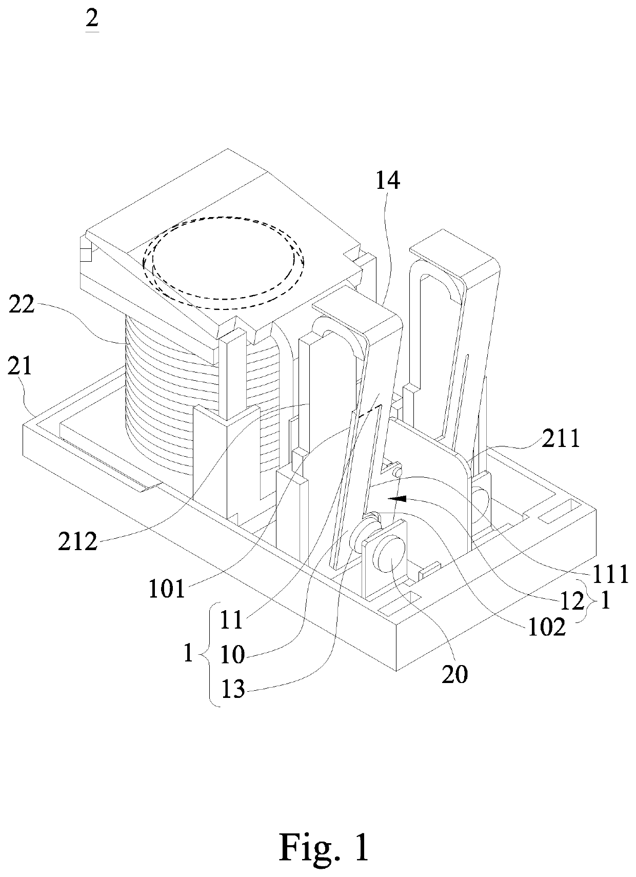
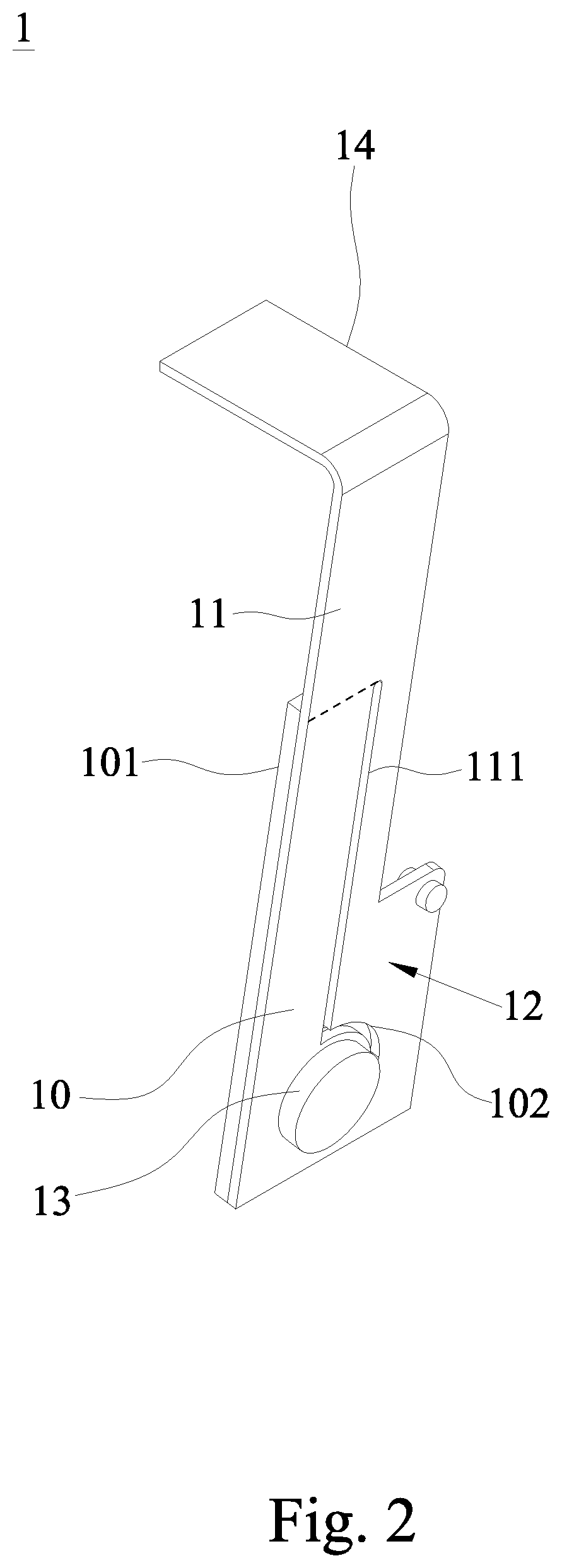
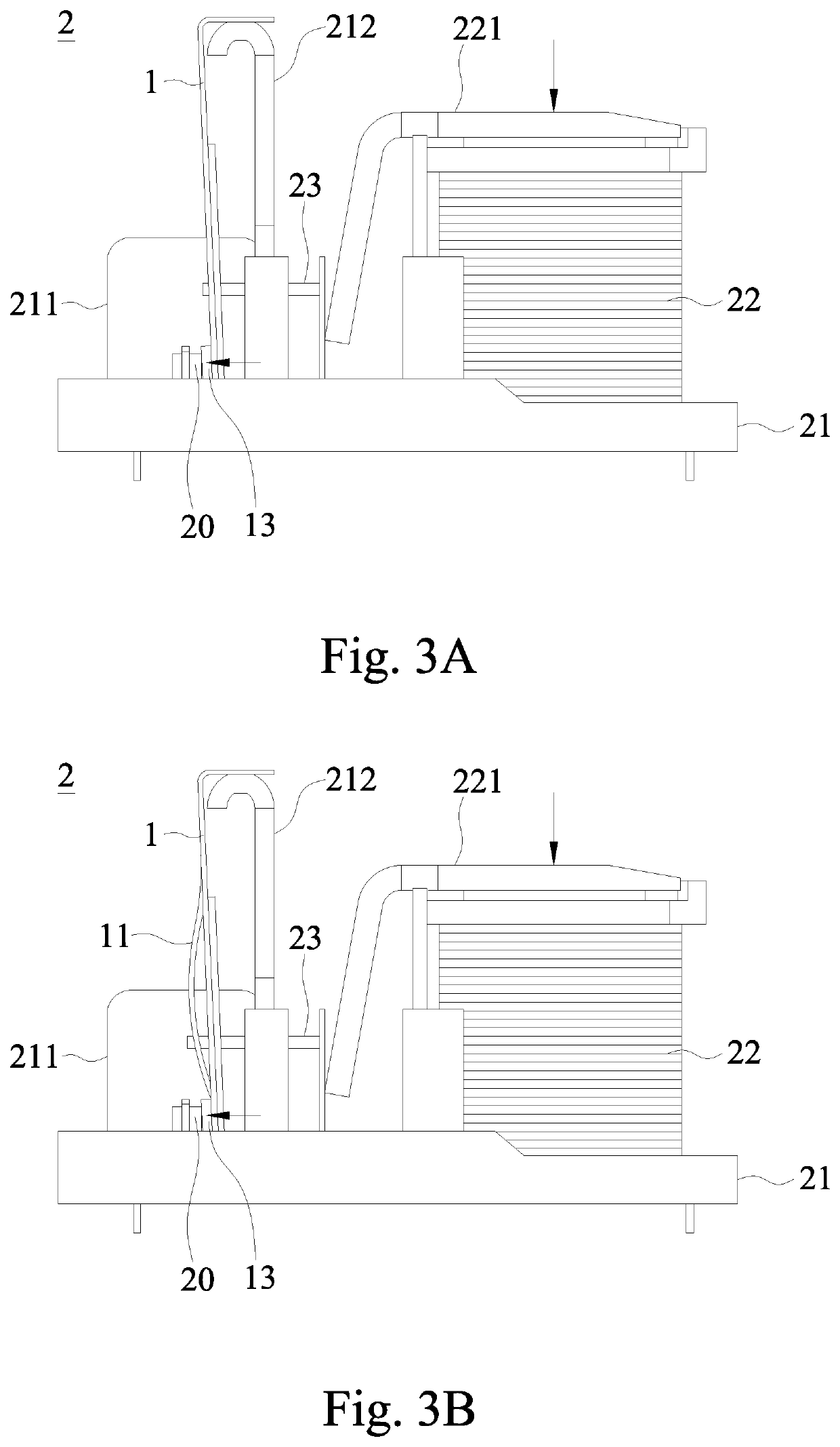
[0023]With reference to FIGS. 1, 2 and 3A to 3C for a perspective view of a relay, a perspective view of a movable spring plate structure, and schematic views of a using status in accordance with a preferred embodiment of the present invention respectively, the present invention discloses a movable spring plate structure 1 and its relay 2 capable of extinguish electric arcs to improve the performance and life of the relay 2. The relay 2 comprises at least one the movable spring plate structure 1, a base 21, at least one electromagnetic structure 22, and a pushing assembly 23. The movable spring plate structure 1 is applied to the relay 2 and provided for defining an open or closed state with respect to a fixed con...


PUM


Abstract

A movable spring plate structure for defining an open or closed state with respect to a fixed contact includes a rigid spring plate contact portion, a soft spring plate warp portion, a soft spring plate force-applying portion and a movable contact. The soft spring plate warp portion is coupled to the rigid spring plate contact portion, and a first deformation gap is formed between the rigid and soft spring plate contact portions. The rigid spring plate contact portion is harder than the soft spring plate warp portion. The soft spring plate force-applying portion is disposed at the soft spring plate warp portion, and the movable contact is disposed at the rigid spring plate contact portion. A force applied to the soft spring plate force-applying portion drives the movable and fixed contacts into a closed state.

Description

FIELD OF INVENTION[0001]The present invention relates to the field of relays, in particular to a movable spring plate structure and its relay capable of extinguishing electric arcs and providing a good conduction contact.BACKGROUND OF INVENTION1. Description of the Related Art[0002]In general, electronic devices are used to help us in our daily life, and relay is one of the most widely used electronic devices. The relay is used to control a smaller current circuit system and control another circuit system by an open or closed state. After an electromagnetic relay is connected to a small current circuit, an electromagnetic device produces an electromagnetic effect to drive a movable connector to contact a fixed connector in the relay in order to conduct another controlled circuit system which is electrically coupled to the connector, and vice versa.[0003]However, when the circuit system controlled by the relay is electrically conducted, the connectors are contacted with each other to...

Claims


Application Information

Patent Timeline
Patent Type & Authority Patents(United States)
IPC IPC(8): H01H1/24H01H51/28H01H9/34H01H50/58H01H50/64H01H51/01
CPCH01H51/01H01H51/287H01H50/64H01H9/34H01H50/58H01H1/502H01H1/54H01H50/54H01H50/641
Inventor WU, SUNG-JEN
Owner SONG CHUAN PRECISION
Why Eureka
Try Eureka