
Battery Module

a battery module and battery technology, applied in the field of batteries, can solve the problems of low mechanical strength, low process efficiency, and difficulty in maintaining a stacked state by itself, and achieve the effects of improving heat transfer efficiency, reducing temperature differences, and fixing cell stacks better

Pending Publication Date: 2022-04-07
LG ENERGY SOLUTION LTD
View PDF0 Cites 0 Cited by
  • Summary
  • Abstract
  • Description
  • Claims
  • Application Information

AI Technical Summary

Benefits of technology

The patent is about a way to use a material called thermal interface material (TIM) to improve heat transfer in battery modules. By wrapping the TIM around the bottom of the battery cell and placing it on a bottom plate, the TIM prevents any leakage and fixes the cell in place. This improves the efficiency of heat transfer and reduces temperature differences across the battery, which can improve its lifespan and performance.

Problems solved by technology

However, a pouch-type secondary battery is generally packaged in a battery case of a laminate sheet of aluminum and polymer resin, and thus the mechanical strength is low and it is not easy to maintain a stacked state by itself.
Accordingly, in the conventional battery module structure, additional costs for the cartridges or fasteners are required, and is difficult to assemble, resulting in low process efficiency.
In addition, the cartridges or fasteners increase the volume of the battery module, making it difficult to reduce the size of the battery module.
In addition, when the temperature of the secondary battery is higher than the optimal temperature, the performance of the secondary battery may degrade, and in worse cases, explosions or fires may occur.
In particular, in a battery module including a stack of pouch-type secondary batteries, the total amount of heat emitted from the secondary batteries in the narrow space may increase the temperature of the battery module faster and more severely.
Moreover, battery modules for use in automobile battery packs may be frequently exposed to direct sunlight and placed in high temperature conditions, for example, summer or desert areas.
That is, in the process of placing the cell stack after applying the TIM to the bottom of the module housing, the TIM leaks out in the front-rear directions of the module housing due to the weight of the cell stack and the viscosity of the TIM.
To prevent the TIM leaks, when the TIM is used in a smaller amount, the TIM does not reach the end of the secondary battery cell body, resulting in poor heat dissipation at the two ends of the secondary battery cell, and as a consequence, a difference in temperature between the central area and the two ends of the secondary battery cell increases, resulting in reduced life and performance of the cell.

Method used


Image

  • Battery Module
  • Battery Module
  • Battery Module

Examples


Embodiment Construction

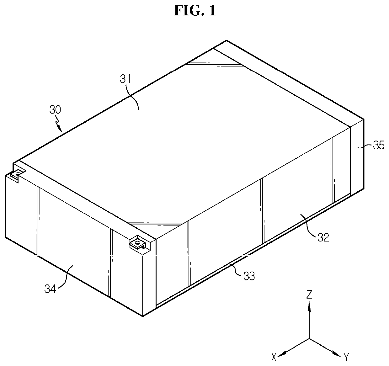
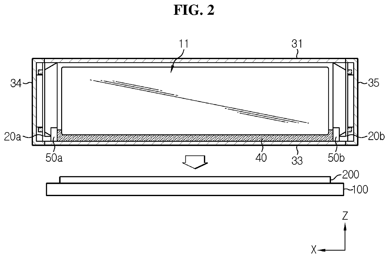
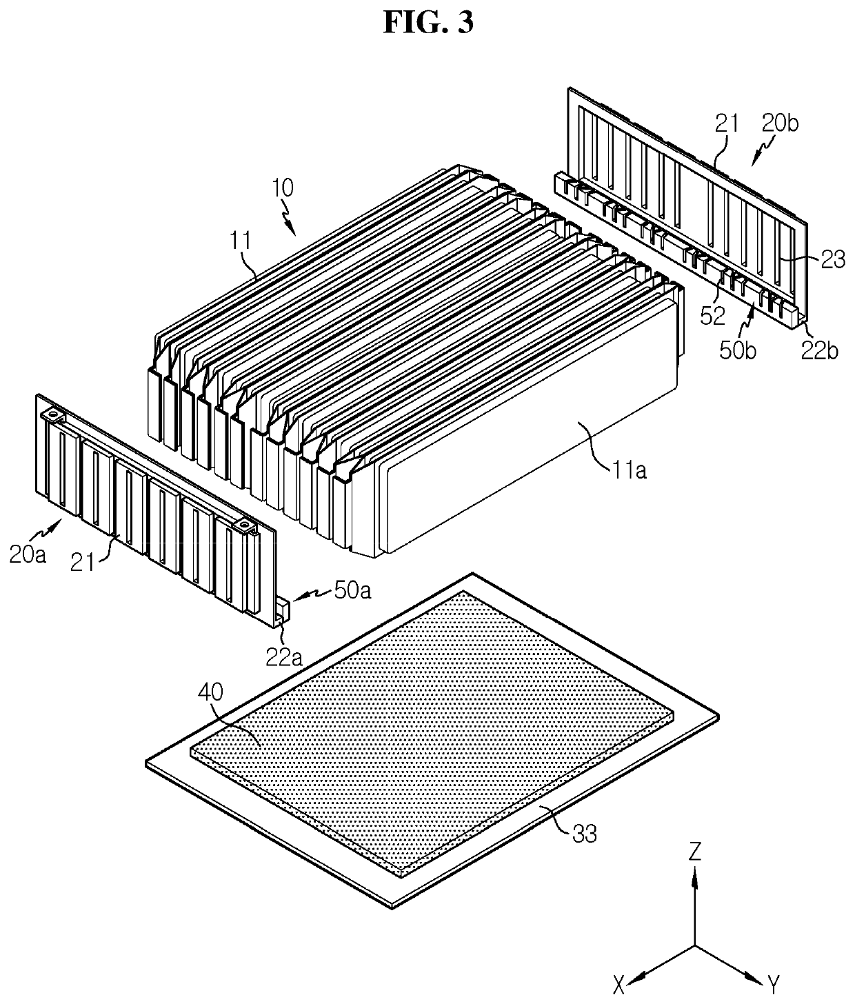
[0037]Hereinafter, the preferred embodiments of the present disclosure will be described in detail with reference to the accompanying drawings. Prior to the description, it should be understood that the terms or words used in the specification and the appended claims should not be construed as being limited to general and dictionary meanings, but rather interpreted based on the meanings and concepts corresponding to the technical aspects of the present disclosure on the basis of the principle that the inventor is allowed to define the terms appropriately for the best explanation. Therefore, the embodiments described herein and illustrations shown in the drawings are just some preferred embodiments of the present disclosure, but are not intended to fully describe the technical aspects of the present disclosure, so it should be understood that a variety of other equivalents and modifications could have been made thereto at the time that the application was filed.

[0038]FIG. 1 is a sche...


PUM

PropertyMeasurementUnit
dimensionaaaaaaaaaa
thermally conductiveaaaaaaaaaa
lengthaaaaaaaaaa

Abstract

A battery module includes a bottom plate to support a cell stack; a busbar frame having a lower end portion bent in an inward direction along an upper surface of the bottom plate and mounted on the front and rear sides of the cell stack; a thermally conductive resin applied to the upper surface of the bottom plate; and a fence member provided at an end of the lower end portion of the busbar frame and disposed on the upper surface of the bottom plate to prevent the leakage of the thermally conductive resin.

Description

CROSS-REFERENCE TO RELATED APPLICATIONS[0001]The present application is a national phase entry under 35 U.S.C. § 371 of International Application No. PCT / KR2020 / 007929 filed on Jun. 18,2020, which claims priority from Korean Patent Application No. 10-2019-0153704 filed on Nov. 26,2019, the disclosures of which are incorporated herein by reference in their entirety.TECHNICAL FIELD[0002]The present disclosure relates to a battery module including pouch-type secondary batteries, and more particularly, a battery module with improved cooling performance by a heat dissipation method through the cell body bottom of pouch-type secondary batteries, and a battery pack and a vehicle including the same.BACKGROUND ART[0003]In general, a secondary battery may be classified into a can-type secondary battery in which an electrode assembly is embedded in a metal can and a pouch-type secondary battery in which an electrode assembly is embedded in a pouch of an aluminum laminate sheet according to the...

Claims


Application Information

Patent Timeline
Patent Type & Authority Applications(United States)
IPC IPC(8): H01M10/653H01M50/505H01M10/613H01M10/625H01M10/647H01M10/6554
CPCH01M10/653H01M50/505H01M10/613H01M2220/20H01M10/647H01M10/6554H01M10/625H01M50/105H01M50/298H01M50/507H01M50/244Y02E60/10H01M50/211H01M50/258H01M50/249B60L50/64B60L58/26
Inventor JIN, HEE-JUNKIM, KYUNG-WOOKIM, KYUNG-MOMUN, JEONG-OPARK, JIN-YONGPARK, JHIN-HACHI, HO-JUNE
Owner LG ENERGY SOLUTION LTD
Learn More