Water-abrasive cutting system

a cutting system and water-abrasive technology, applied in the direction of abrasive machine components, earth drilling and mining, abrasive apparatus, etc., can solve the problems of difficult detection, difficult to detect, difficult to carry out work, etc., and achieve the effect of small stroke length of the movable contact element and positive engagemen

Active Publication Date: 2020-01-07
ANT APPLIED NEW TECH
View PDF33 Cites 5 Cited by
  • Summary
  • Abstract
  • Description
  • Claims
  • Application Information

AI Technical Summary

Benefits of technology

[0008]Particularly preferably the at least one further sensor is at least one acoustic emission sensor, at least one acceleration sensor and / or at least one pressure sensor. Further preferred is a combination of hydrophone, acoustic emission sensor, acceleration sensor as well as a pressure sensor. The cutting monitoring device or its evaluation device is preferably configured so that it detects a complete penetration and / or cutting-through of a wall or pipe wall on the basis of the sensor signals of the acoustic emission sensor, the acceleration sensor, the hydrophone and the pressure sensor. To this end all these sensors are connected to the cutting monitoring device or its evaluation device for data transmission. The use according to the invention of at least two, preferably four different sensors, namely particularly preferably the hydrophone, an acoustic emission sensor, an acceleration sensor and a pressure sensor allows a substantially more accurate detection of the penetration and cutting-through of the wall than would be possible using only a hydrophone, as a result of the simultaneous evaluation and comparison of different signals. It is thus possible to make defined settings in the evaluation device that the signals of different sensors must together have certain desired values or variations in order to detect a successful penetration or cutting-through of the wall.
[0015]According to a particularly preferred embodiment of the invention, the fixing device comprises several, preferably three contact elements distributed over the circumference of the cutting head, which can come in contact with a pipe wall for fixing. This configuration of the fixing device can be used independently of the previously described cutting monitoring device, that is even without this cutting monitoring device. This also applies to the details of the fixing device described hereinafter. As a result of the arrangement of a plurality of, preferably three contact elements, it is possible to brace the fixing device firmly in the interior of the pipe by pressing the contact elements in the radial direction towards the inner wall of the pipe. Furthermore, a positioning of the cutting head spaced apart from the inner wall of the pipe, in particular a centered arrangement is thus possible. Particularly preferably the plurality of contact elements, for example, the three said contact elements, are distributed uniformly over the circumference of the cutting head, thus a uniform transmission of force between cutting head and pipe wall is obtained. Furthermore the contact elements preferably lie in a cross-sectional plane normal to the longitudinal or advance axis of the cutting head. This longitudinal axis corresponds to the longitudinal axis of the pipe to be cut through.
[0017]Further, preferably two of the contact elements are configured to be rigid in the radial direction and preferably are fastened exchangeably on the cutting head. This applies in particular when overall three contact elements are provided. In this configuration, preferably two contact elements are then configured to be rigid whilst the third contact element is movable radially in the previously described manner. As a result of the movement of the movable contact element, in this embodiment a bracing of the cutting head in the pipe is possible since the movable contact element is pressed against the inner wall of the pipe. As a reaction, the two rigid contact elements are pressed at the same time onto the pipe wall in the opposite direction. The rigid contact elements are preferably configured to be exchangeable. For this purpose contact elements having different radial length are provided so that it is possible to adapt the cutting head to different inside diameters of pipes. Thus, for larger pipe cross-sections in the radial direction, longer contact elements can be provided than for smaller pipe diameters. Thus, for different pipe diameters an approximate centering of the cutting head is always possible. Furthermore, the required stroke length of the movable contact element can be kept small.
[0018]According to a further preferred embodiment, the contact elements are configured to be sled-shaped, where the contact elements extend in their sled-shaped longitudinal extension parallel to the direction of advance of the cutting head in a pipe. Thus, the contact elements can guide the cutting head during insertion into a pipe in the interior of the pipe. A canting of the cutting head in the pipe during the advance is thus avoided.
[0019]According to a particular embodiment of the invention, at least one of the contact elements and preferably all the contact elements on a surface provided for contact on a pipe wall, that is the inner wall of the pipe, can comprise engagement means for positive engagement in the pipe wall. This can, for example, be a fluting or an arrangement of prongs which digs into the pipe wall and achieves a positive engagement in addition to the non-positive contact. A better fixing of the cutting head in the interior of the pipe can thereby be achieved.

Problems solved by technology

A problem with these cuts is that the work must be carried out without visual monitoring and therefore it is difficult to detect whether the pipe wall has been completely cut through this means in the radial direction and is completely cut through over the entire circumference.
This is particularly difficult to detect since these pipes are usually configured as multi-shell, comprising a plurality of metal pipes lying inside one another, where the intermediate spaces of the metal pipes are filled with concrete.
At the same time however the pipes are not always arranged in a centered manner and the intermediate spaces are not always completely filled so that no uniform cutting conditions are given.
In particular in the multi-shell pipes described however, a reliable detection of the cutting-through is not always ensured, which is in particular attributable to the fact that the filling of the intermediate spaces between the individual pipes and also the material which surrounds the pipe on the outer side is not known and depending on these states, different noises can be detected which do not always indicate a complete cutting-through of the pipe wall.

Method used


Image

  • Water-abrasive cutting system
  • Water-abrasive cutting system
  • Water-abrasive cutting system

Examples


Embodiment Construction

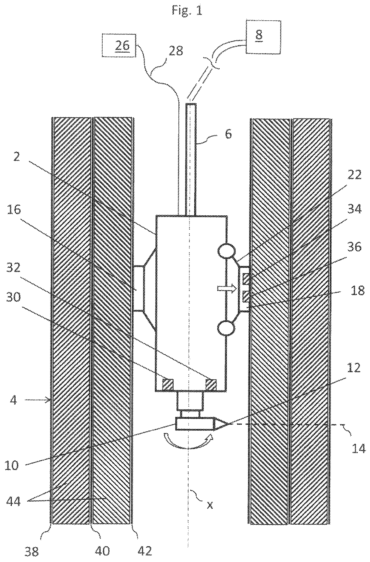
[0033]Referring to the drawings, the shown water-abrasive cutting system is a water-abrasive suspension cutting system, that is a cutting system in which the abrasive agent is added to the water in the high-pressure region upstream of a cutting nozzle. The cutting system according to the invention comprises a cutting head 2 which is configured for insertion into a pipe 4. The cutting head 2 is connected via a pressure line 6 to a supply unit 8. The supply unit 8 comprises in particular a high-pressure pump which provides water at high pressure, for example, a pressure of 2500 bar or higher. Furthermore the supply unit 8 has an abrasive agent supply. The suspension at high pressure, that is a water-abrasive agent mixture, is supplied via the pressure line 6 to the cutting head 2. During operation the supply unit 8 remains outside the pipe. In offshore applications the supply unit 8 preferably remains above the water surface whilst the cutting head 2, for example, is introduced so far...


PUM

PropertyMeasurementUnit
pressureaaaaaaaaaa
rotationaaaaaaaaaa
circumferenceaaaaaaaaaa

Abstract

A water-abrasive cutting system includes a cutting head (2) which includes a fixing device (16, 18, 20) for fixing the cutting head (2) on the wall to be cut as well as a nozzle head (10) disposed on the cutting head (2). At least one cutting nozzle (12), for an application of a cutting jet (14), is disposed in the cutting head (2). A cutting monitoring device (26) includes at least one hydrophone (30) and at least one further sensor. The cutting monitoring device (26) is configured to detect a complete penetration and / or cutting-through of the wall on the basis of the sensor signals of the hydrophone (30) and the at least one further sensor.

Description

CROSS REFERENCE TO RELATED APPLICATIONS[0001]This application is a United States National Phase Application of International Application PCT / EP2015 / 053432, filed Feb. 18, 2015, the entire contents of which are incorporated herein by reference.FIELD OF THE INVENTION[0002]The invention relates to a water-abrasive cutting system, for cutting pipes, having a cutting head which comprises a fixing device for fixing the cutting head on the wall to be cut as well as a nozzle head disposed on the cutting head, in which at least one cutting nozzle for application of a cutting jet is disposed.BACKGROUND OF THE INVENTION[0003]Water-abrasive cutting systems are used for the cutting of various materials and objects. For example, they are used for cutting pipes, in order, for example to cut oil carrying pipes under the seabed. Such cutting systems can however also be used for cutting pipes in other applications, for example, refineries, well building etc. Furthermore, not only pipes but also objec...

Claims


Application Information

Patent Timeline
Patent Type & Authority Patents(United States)
IPC IPC(8): B24C1/04B24C3/32E21B29/00B24C9/00
CPCB24C3/325B24C3/32E21B29/002E21B29/00B24C9/00B24C1/045E21B29/005
Inventor LINDE, MARCO
Owner ANT APPLIED NEW TECH
Why Eureka
Try Eureka