
Beam combining for highlight projection

a beam-combining and highlight technology, applied in the field of image projection systems and methods, can solve the problems of high cost, high cost, and high complexity of 3d projection systems, and achieve the effects of increasing the brightest parts (highlights), and reducing the cost of production

Active Publication Date: 2020-01-07
DOLBY LAB LICENSING CORP
View PDF46 Cites 2 Cited by
  • Summary
  • Abstract
  • Description
  • Claims
  • Application Information

AI Technical Summary

Benefits of technology

[0006]The present invention overcomes the problems associated with the prior art by providing projection systems and methods that increase the brightest parts (highlights) of the projected imagery with minimal complication and additional cost. Embodiments of the invention facilitate adding highlights to 2D images, as well as, adding highlights to the individual left- and right-eye views of projected 3D images.
[0010]Various light sources can be used with the invention. In one embodiment, the first light source includes a first set of primary lights (lasers), and the second light source includes a second set of primary lights having a different spectral composition than the first set of primary lights. In another embodiment, the first light source includes a first white light source, and the second light source includes a second white light source, where the first white light has different wavelength bands of red, green, and blue light than the second white light source. In some embodiments, the controller is operative to cause the second light source / set of primary lights to be selectively energized responsive to the image data being received on the image data input.
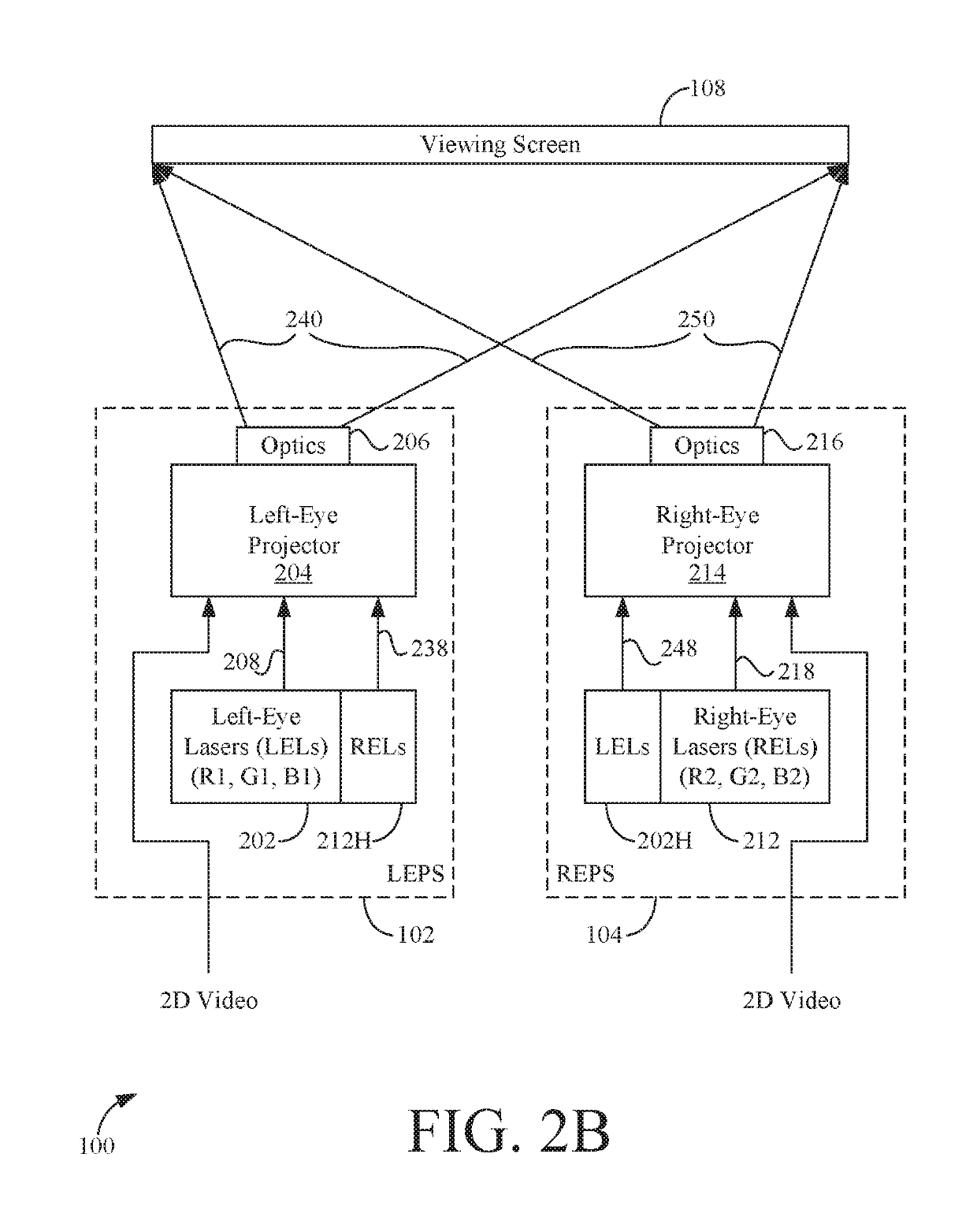
[0013]The image data can be 2D image data or 3D image data. Additionally, in some methods, the step of receiving image data can include sometimes receiving 2D image data and other times receiving 3D image data, for example, based on a 2D or 3D display mode. In such a case, a particular method can include illuminating the beam steering device with light from the second light source responsive to receiving the 2D image data. In other methods, such as those associated with a 3D-capable projection system, the first light source can be associated with a first-eye view present in the image data when the image data comprises 3D image data, the second light source can be associated with a second-eye view present in the image data when the image data comprises 3D image data, and the second light source can have different spectral characteristics than the first light source. Still other methods include polarizing the highlighted imaging beam (e.g., with a light doubler, etc.), for example, to facilitate separation of the left- and right-eye views.

Problems solved by technology

3D projection systems are very complex and thus expensive.
Projections systems that have low peak brightness are not able to represent such scenes very realistically, because the bright regions do not appear bright enough to the viewer.
However, the highlight projector represents a significant additional cost to the movie theater, especially in view of the already-expensive 3D projection systems, which often require multiple projectors.
Furthermore, the highlight projector must remain aligned with the main projector(s) for the highlighted images to appear realistic and undistorted, which adds yet another on-going maintenance cost and time burden on the movie theater.

Method used


Image

  • Beam combining for highlight projection
  • Beam combining for highlight projection
  • Beam combining for highlight projection

Examples


Embodiment Construction

[0040]The present invention overcomes the problems associated with the prior art by providing projection systems and methods that increase the brightest parts (highlights) of the projected imagery with minimal complication and additional cost. In the following description, numerous specific details are set forth (e.g., particular control modules, particular highlighting routines, etc.) in order to provide a thorough understanding of the invention. Those skilled in the art will recognize, however, that the invention may be practiced apart from these specific details. In other instances, details of well-known projection practices (e.g., modulator control, routine optimization, etc.) and components have been omitted, so as not to unnecessarily obscure the present invention.

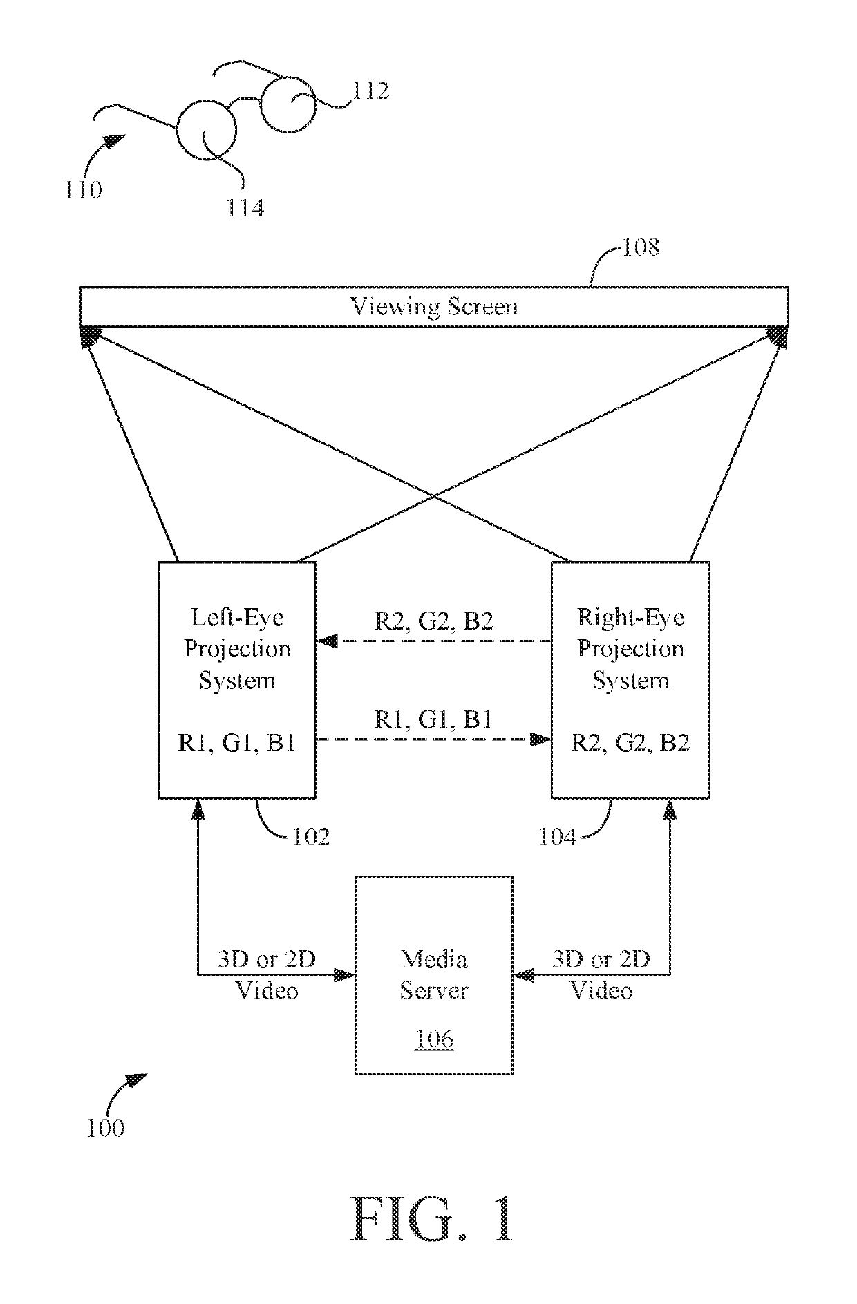
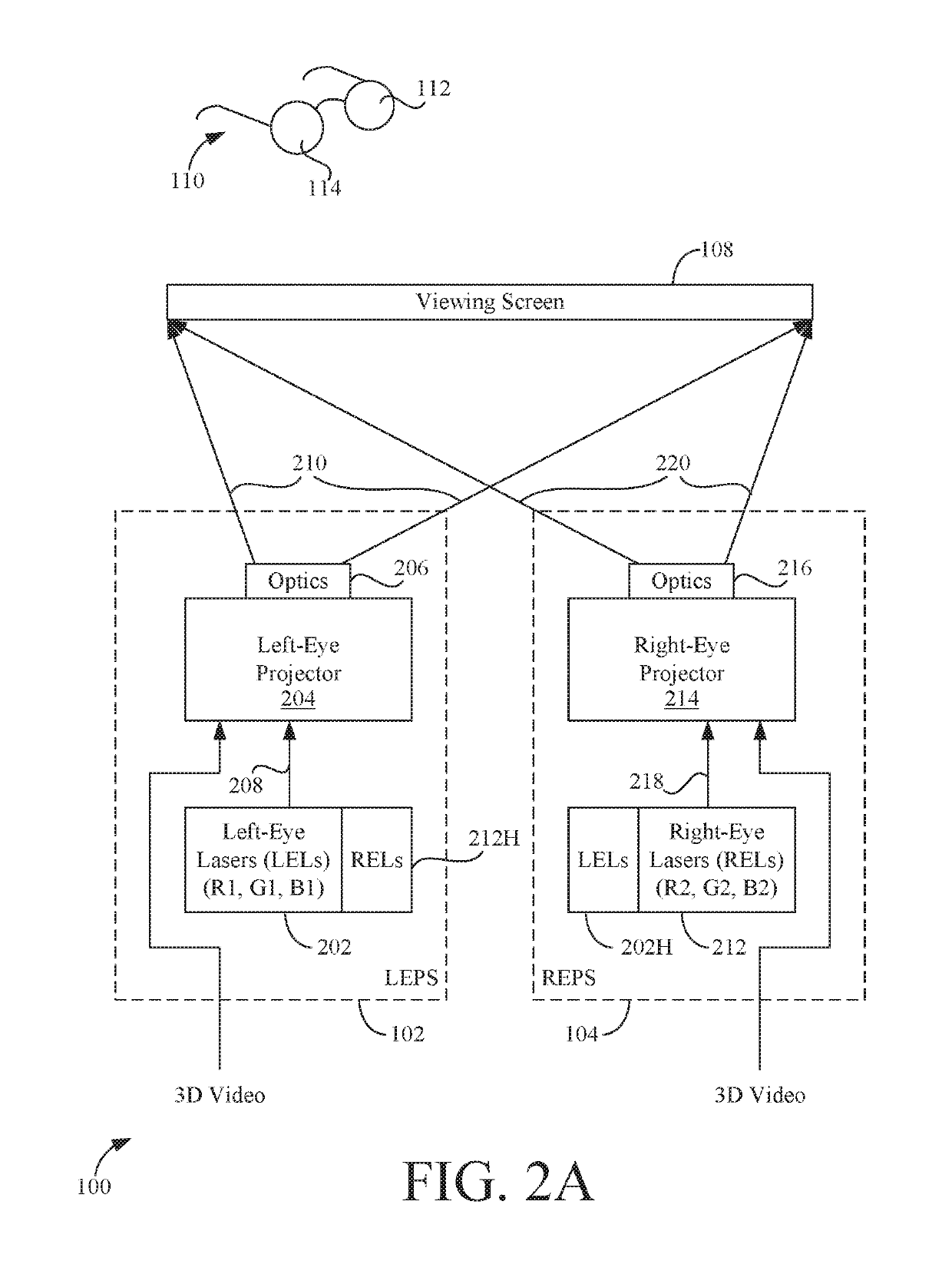
[0041]FIG. 1 is a block diagram showing a three-dimensional (3D) projection system 100 according to one embodiment of the present invention. 3D projection system 100 includes a left-eye projection system (LEPS) 102 a...


PUM


Abstract

A novel projection system includes first and second light sources (e.g., sets of lasers), a spatial light modulator (SLM) that receives light from the first light source, and a beam steering device that receives light from the second light source and steers the light to highlight regions of the SLM. The SLM then modulates the light from both light sources to generate a highlighted imaging beam which can then be projected on a viewing surface. The highlighted imaging beam can represent a highlighted 2D image or a highlighted left- or right-eye view of a 3D image. The projection system thus improves peak brightness in the displayed highlighted images without incorporating a separate highlight projector or other expensive equipment. Methods for highlighting projected images are also described.

Description

BACKGROUND[0001]Technical Field[0002]This invention relates generally to image projection systems and methods, and more particularly to image projection systems and methods that improve highlights in projected images.[0003]Description of the Background Art[0004]Video projection systems for use in movie theaters (cinemas) and home theaters are known. While home theater systems usually are capable of displaying only two-dimensional (2D) images, projection systems in movie theaters are often capable of displaying three-dimensional (3D) video. 3D projection systems are very complex and thus expensive. They represent a significant capital investment for the cinema, especially if the 3D projection system is being used to show both 3D and 2D films and is operating in 2D mode a significant portion of the time.[0005]It is also a goal of all projection systems to provide realistic imagery. An important component in realizing this goal is increasing the peak brightness capable of being produce...

Claims


Application Information

Patent Timeline
Patent Type & Authority Patents(United States)
IPC IPC(8): H04N9/31H04N13/334H04N13/363H04N13/356G03B21/20H04N13/337H04N13/359H04N13/339H04N13/341H04N13/351H04N13/332
CPCH04N13/339H04N9/3155H04N9/3105H04N13/332H04N13/356H04N9/3132H04N9/3161H04N13/334H04N13/351H04N13/359H04N13/363H04N9/315H04N13/337H04N9/3126G03B21/2033H04N13/341H04N9/3164H04N9/3147
Inventor RICHARDS, MARTIN J.LIPPEY, BARRET
Owner DOLBY LAB LICENSING CORP
Learn More