Face plate in transparent optical projection displays

a transparent optical projection and display image technology, applied in the direction of spectacles/goggles, bundled fibre light guides, instruments, etc., can solve the problems of inability to achieve aircraft use certification, inability to achieve gpus work as intended, time and cost, etc., to achieve the effect of transferring the image part, not taking up a lot of space, and good quality of the display image par

Active Publication Date: 2020-01-21
SAAB AB
View PDF17 Cites 0 Cited by
  • Summary
  • Abstract
  • Description
  • Claims
  • Application Information

AI Technical Summary

Benefits of technology

[0028]According to some aspects, the image sensor comprises two or more image sensors and the fiber optic face plate comprises two or more fiber optic face plates, each abutting against a separate part of the display image at a focused image plane, wherein each fiber optic face plate transfers the corresponding part of the display image from the focused image plane to a corresponding image sensor. The advantage of this is the same as the corresponding feature for the display image monitor.
[0029]The objects of the disclosure is further obtained by a method performed in a transparent optical projection display for monitoring a display image, the transparent optical projection display comprising a combiner system, an image producing arrangement, and a display image monitor comprising a fiber optic face plate and an image sensor. The method comprises transferring at least one part of a display image of the transparent optical projection display at a focused image plane to the image sensor using the fiber optic face plate and analyzing the sensor data of the at least one part of the display image from the image se...

Problems solved by technology

If the information on the display is misleading, this could result in fatal maneuvers.
Examples of misleading information are wrong height information, wrong targeting information or a wrong horizon.
Further misleading operation could be that important symbols overlap so that they are not readable, or at least not readable without any difficulties.
Developing G...

Method used


Image

  • Face plate in transparent optical projection displays
  • Face plate in transparent optical projection displays
  • Face plate in transparent optical projection displays

Examples


Embodiment Construction

[0051]Aspects of the present disclosure will be described more fully hereinafter with reference to the accompanying drawings. The apparatuses and methods disclosed herein can, however, be realized in many different forms and should not be construed as being limited to the aspects set forth herein. Like numbers in the drawings refer to like elements throughout.

[0052]The terminology used herein is for the purpose of describing particular aspects of the disclosure only, and is not intended to limit the disclosure. As used herein, the singular forms “a”, “an” and “the” are intended to include the plural forms as well, unless the context clearly indicates otherwise.

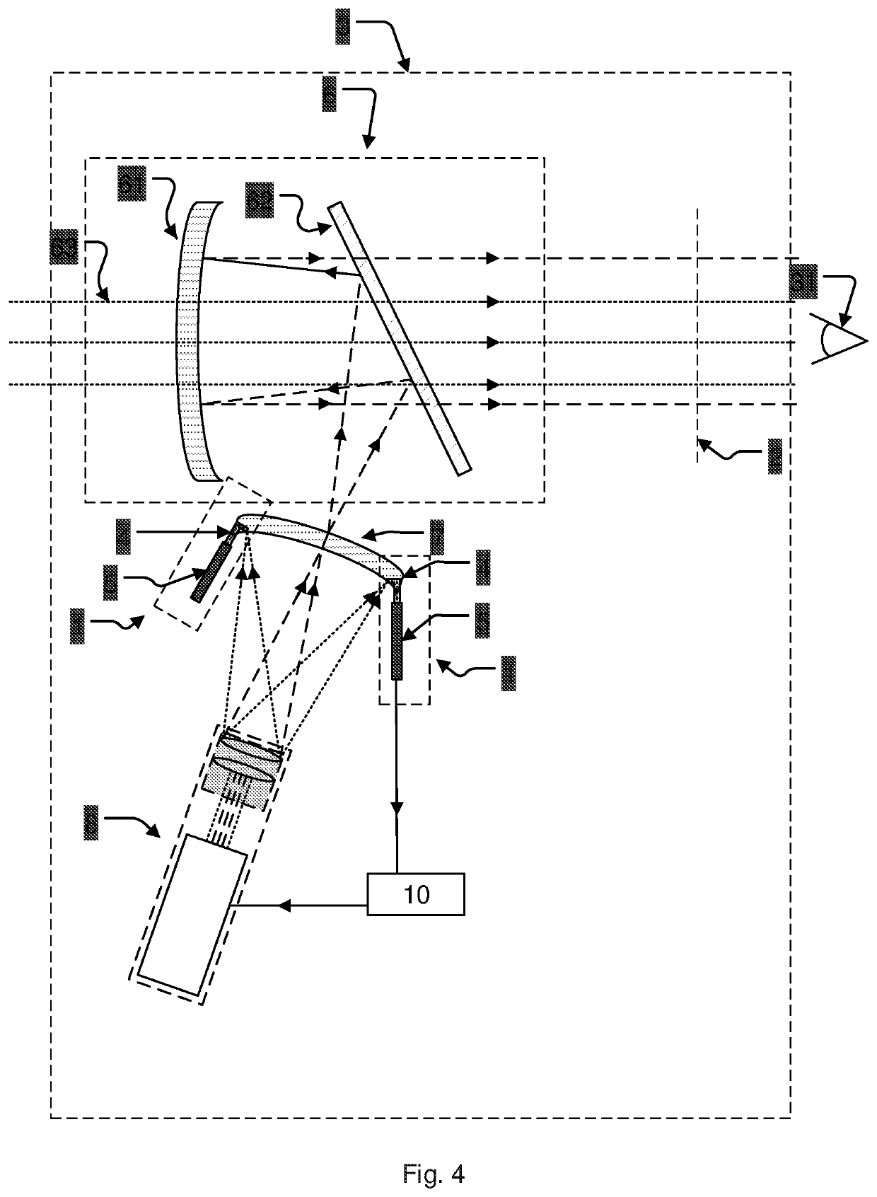
[0053]It should be noted that the term transparent optical projection display relates to all types of transparent displays with optical projection. Such displays are for example Head Up Displays, HUDs, or Helmet Mounted Displays, HMDs. The disclosed technology is sometimes throughout the description described using a HUD syste...


PUM


Abstract

The present disclosure relates devices and a method for monitoring a display image (2) in a transparent optical projection display. They disclose a display image monitor (1) comprising a fiber optic face plate (4) and an image sensor (5). The fiber optic face plate (4) comprises a first surface (4a) with optic fiber ends and a second surface (4b) with corresponding optic fiber ends and transfers light from the first surface (4a) to the second surface (4b) through the optic fibers, wherein the first surface abuts against a part (2a) of the display image (2) at a focused image plane (2b) and thus the light of the part of the display image enters the optic fiber ends and wherein the second surface is arranged to direct the part of the display image to the image sensor, thereby transferring the part of the display image to the image sensor.

Description

CROSS REFERENCE TO RELATED APPLICATIONS[0001]This application is a National Stage Application, filed under 35 U.S.C. § 371, of International Application No. PCT / SE2016 / 050001, filed Jan. 5, 2016; the contents of which as are hereby incorporated by reference in their entirety.BACKGROUND[0002]Related Field[0003]The present disclosure relates devices and a method for monitoring a display image in a transparent optical projection display. In particular the disclosure relates to devices and a method related to transparent optical projection displays, for monitoring the display image with a fiber optic face plate and an image sensor.[0004]Description of Related Art[0005]It is important that displays, especially transparent optical projection displays such as Head Up Displays, HUD, or Helmet Mounted Displays, HMD, show right information for a commander of a vehicle, such as a pilot of an aircraft. If the information on the display is misleading, this could result in fatal maneuvers. Exampl...

Claims


Application Information

Patent Timeline
IPC IPC(8): G02B6/00G02B5/02G02B6/08G02C7/08G02B27/01
CPCG02C7/086G02B6/08G02B5/0278G02B27/0172G02B2027/011G02B2027/0138G02B2027/013G02B2027/014G02B27/0101
Inventor HOLMER, ANNA-KARINZANDEN, JOHANANDERSSON, STEFAN
Owner SAAB AB
Why Eureka
Try Eureka