Biometric identification headpiece system for test taking

a headpiece system and biometric identification technology, applied in the field of computer-based system and method for taking a test, can solve the problems of enormous value for students, and achieve the effect of secure test taking

Active Publication Date: 2020-01-21
INTELLIGENT TECH INT
View PDF116 Cites 4 Cited by
  • Summary
  • Abstract
  • Description
  • Claims
  • Application Information

AI Technical Summary

Benefits of technology

[0008]In one embodiment, each light valve assembly allows light transmission therethrough only in a limited angular range to enable the person to see through the light valve assembly when the frame is supported on the person's head and to prevent viewing through the light valve assembly by a person other than the person on which the frame is supported when the frame is supported on the person's head. The light valve assembly may be situated rearward of part of the viewing portion.
[0011]One aspect is to prevent access to a device which the student is using to take a test. A method for detecting an attempt to physically alter an electronic device in accordance with the invention is a type of chassis intrusion detector. In the method, the device, such as glasses used for viewing the test during test-taking, is enclosed in a thin film containing conductive wires which are positioned to surround the device (i.e., not part of the internal wiring of the device). Impedance of the wires is monitored by means of a security assembly (e.g., resistance and / or mutual inductance between a pair of wires). When a change in impedance is detected by the security assembly, a required security code needed for use of the device is deleted. In a preferred embodiment, the device is a glasses assembly being used for test-taking and thus with the method incorporated into the device, secure test taking is provided.

Problems solved by technology

Thus, the value to the student is enormous.

Method used


Image

  • Biometric identification headpiece system for test taking
  • Biometric identification headpiece system for test taking
  • Biometric identification headpiece system for test taking

Examples


Embodiment Construction

[0026]For a general background of this invention, see WO2016028864 Secure testing device, system and method, which is incorporated herein by reference in its entirety.

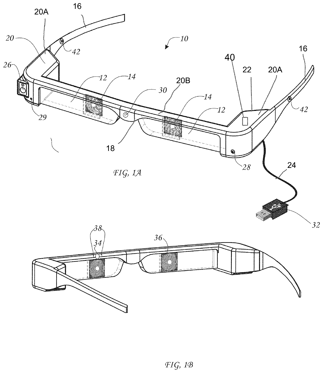
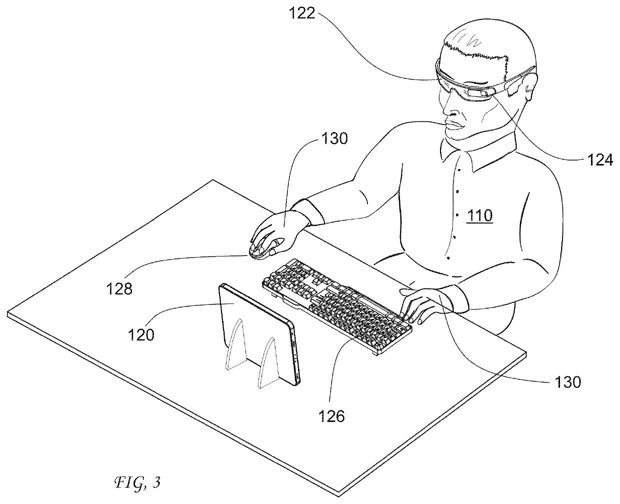
[0027]Referring now to FIGS. 1A and 1B, this embodiment does not require a special laptop or other special computer to facilitate secure test-taking. Rather, in this embodiment, the test-taker can use a desktop or laptop computer, smartphone, tablet or other non-specialized computing device which is compatible with the teaching institution's systems. However, other components are required including a head-mounted apparatus or viewing glasses.

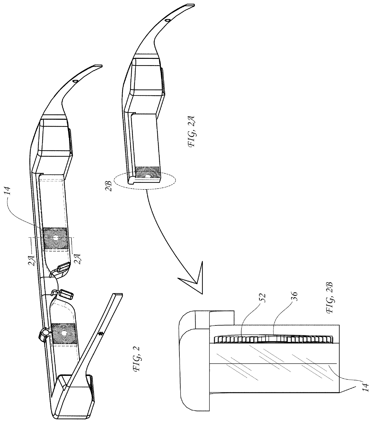
[0028]FIG. 1A illustrates one implementation of the invention, shown generally at 10, which includes view control glasses 12. The view control glasses 12 comprise a viewable window or light valve assembly 14 which is part of one or both glasses lenses, i.e., viewing portions present on either side of a nosepiece that may be made of a transparent material such as glass or a suitable...


PUM


Abstract

Headpiece for test-taking includes a frame having support structure for supporting the frame on a person's head and a viewing portion configured to be in front of the person's face when the frame is supported on the person's head, and at least one light valve assembly arranged in the viewing portion. Each light valve assembly has a first state in which the person is able to see therethrough and an alternative second state in which viewing therethrough is prevented. A controller controls whether the light valve assembly is in the first state or the second state to thereby control viewing therethrough. The light valve assembly may be situated rearward of part of the viewing portion. Only the headpiece wearer is thus able to view test questions on a display through the light valve assembly.

Description

CROSS REFERENCE TO RELATED APPLICATIONS[0001]This application is a continuation-in-part of U.S. patent application Ser. No. 14 / 448,598 filed Jul. 31, 2014 and a continuation-in-part of U.S. patent application Ser. No. 15 / 329,243 filed Jan. 25, 2017 which is a National Stage filing of International Application No. PCT / US15 / 45846 filed Aug. 19, 2015, now expired, which claims the benefit of U.S. provisional patent application Ser. No. 62 / 040,806 filed Aug. 22, 2014, now expired, all of which are incorporated by reference herein.FIELD OF THE INVENTION[0002]The present disclosure relates to the field of a computer-based system and method for taking a test while ensuring that the test-taker is not receiving assistance from another person while taking the test and optionally ensuring that the device being used for viewing or taking the test has not been and is not being tampered with or otherwise compromised. Additionally, the present invention relates to the field of glasses which permit...

Claims


Application Information

Patent Timeline
Patent Type & Authority Patents(United States)
IPC IPC(8): G09B7/077G06F21/88G09B7/00G06F21/32G06F21/86G06K9/00G06F3/01G06F21/62G06F21/84G02B27/01G02B27/00H04R29/00
CPCG06K9/0061G06K9/00604G06F21/32G02B27/017G02B27/0093G06F21/6209G06F21/86G09B7/00G06F3/013G06F21/84G09B7/077G06F21/88H04R2499/15G02B2027/0178G02B2027/0187G06F2221/2151H04R29/004G02B2027/0138G06V40/19G06V40/193
Inventor BREED, DAVID S
Owner INTELLIGENT TECH INT
Why Eureka
Try Eureka