Security Camera System and Method of Steering Beams to Alter a Field of View

a technology of security cameras and beams, which is applied in the field of security cameras, can solve the problems of reducing the contrast and resolution of the resulting image, unable to determine the camera view or operation, and distortion produced entirely by the steering of the prism, so as to achieve fast reaction, reduce the aperture, and facilitate the effect of viewing the camera aim

Active Publication Date: 2009-03-26
HARRIS CORP
View PDF45 Cites 28 Cited by
  • Summary
  • Abstract
  • Description
  • Claims
  • Application Information

AI Technical Summary

Benefits of technology

[0006]
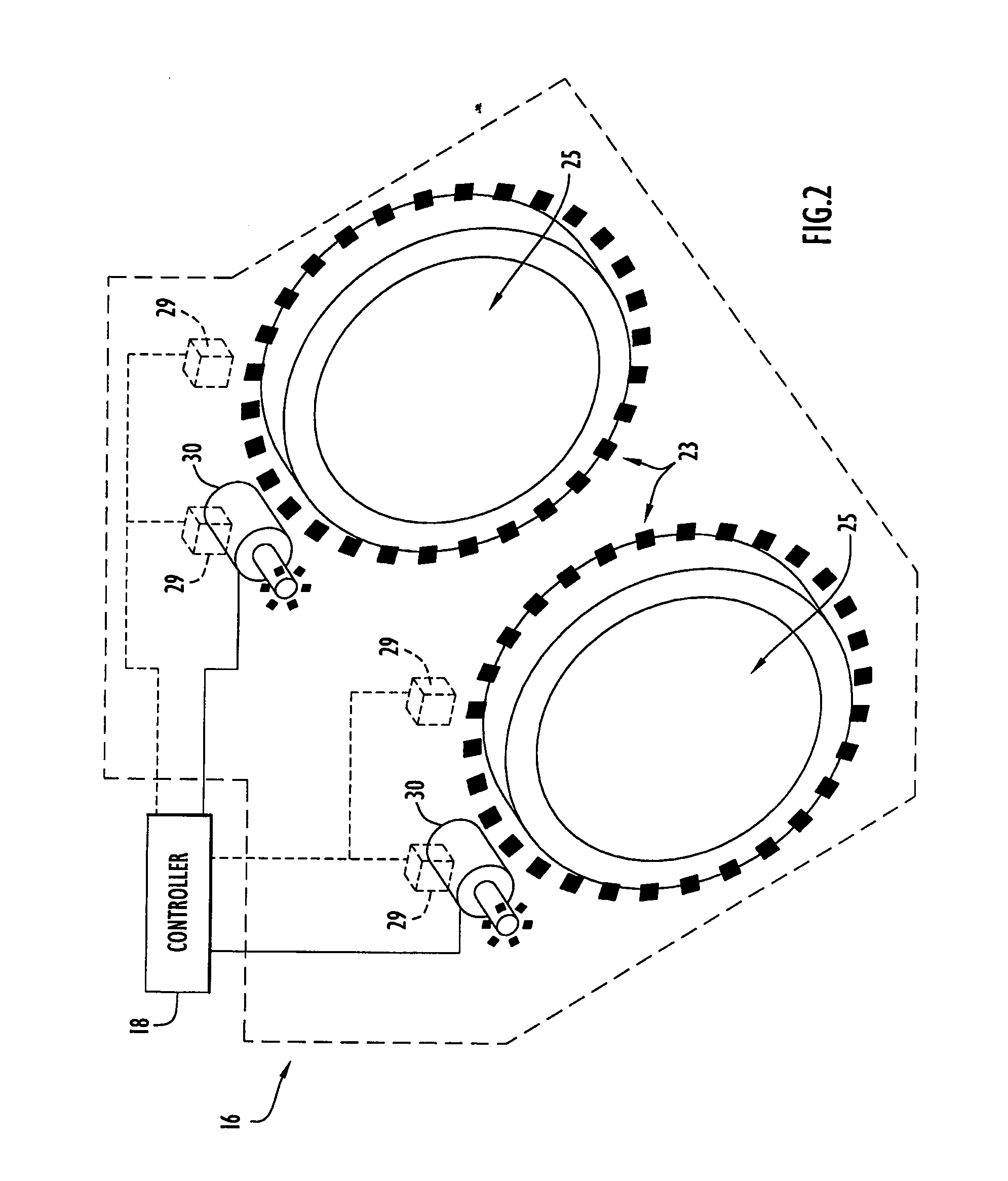
Prism-based beam steering for imaging applications introduces various effects to the resulting image. For example, dispersion effects of the prisms reduce the contrast and resolution of the resulting image. Accordingly, the prisms may include gratings applied to one of the surfaces, thereby creating a “grism”. The grism is specifically designed for the application to control dispersion over the spectral range of interest. A further effect of prism beam steering includes field distortion. In particular, a beam becomes compressed along the axis of steering as the prisms steer the beam. This creates a “squashed” appearance to the image. For example, a camera with an initially wide field of view (e.g., 60°) experiences up to approximately 15% distortion at the edges, but no distortion at the center. However, a camera with a 1° field of view experiences essentially no distortion as a function of field angle. In this case, the distortion is produced entirely from the steering of the prisms. By way of example, a 1° field of view with a steering angle of 45° includes a nearly uniform image distortion of approximately 30% appearing as a squashing of the image along the axis of steering. These effects are addressed by the present invention embodiments through the use of image processing techniques (e.g., a processor with image manipulation software). The processor (with image manipulation software) may be embedded within the security camera architecture and adjustments to images are made prior to the security camera system providing the resulting images. The processor takes into account the beam steering angle and the field of view of the security camera system.
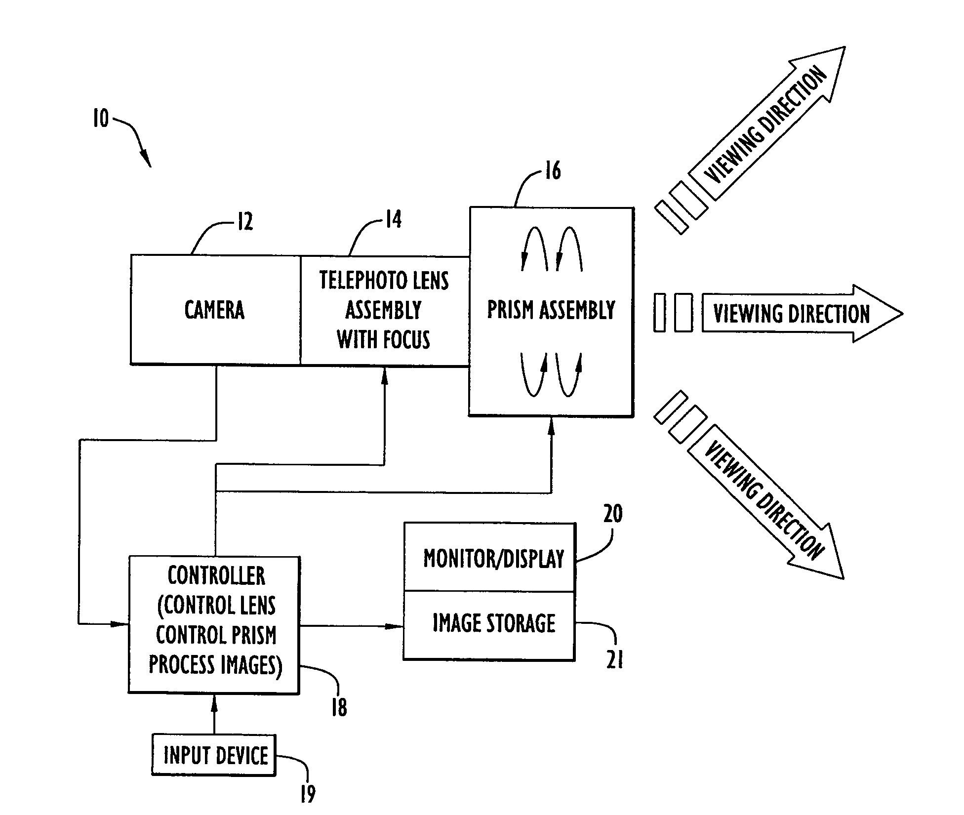
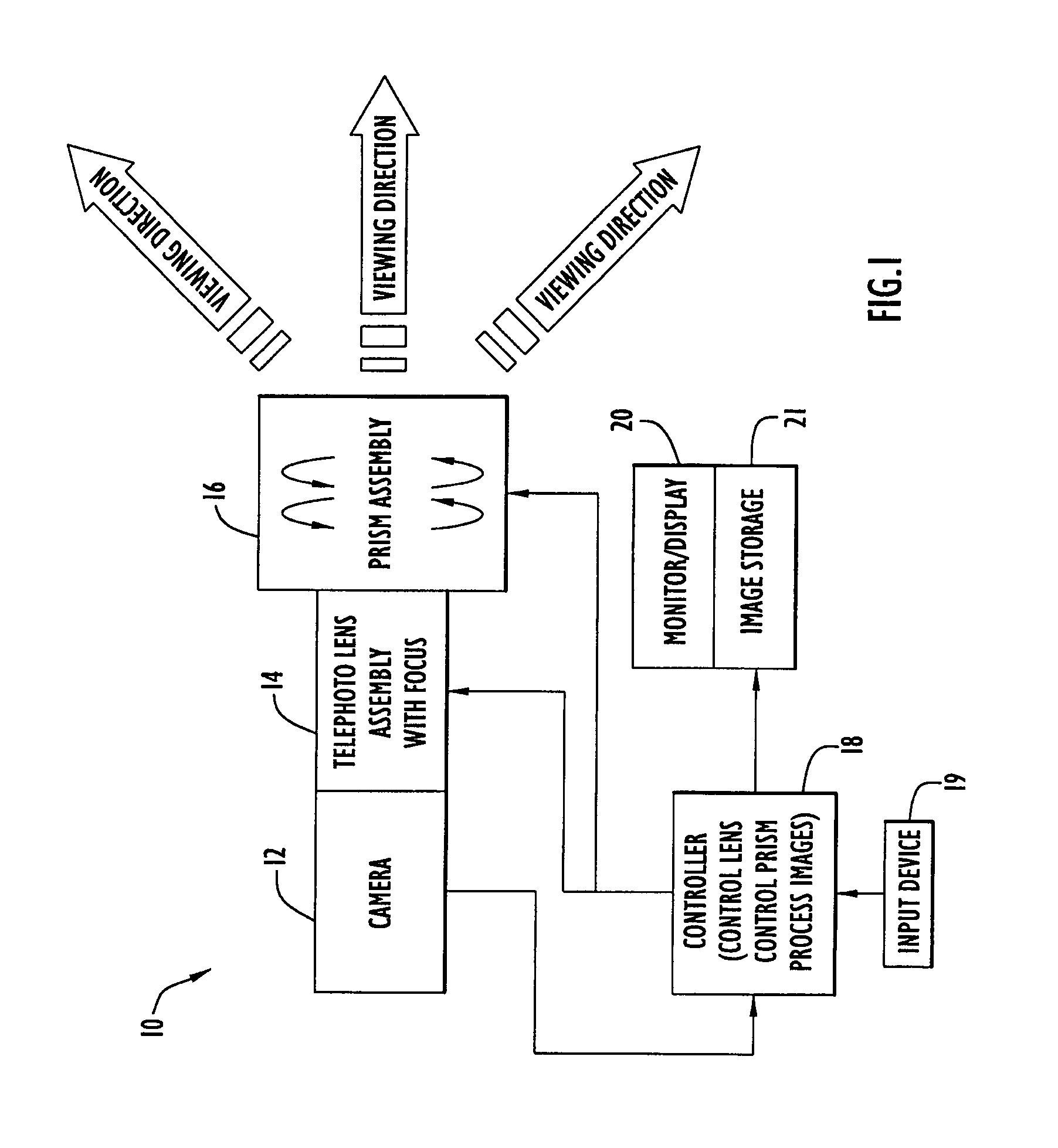
[0008]The present invention embodiments provide several advantages. In particular, the present invention embodiments essentially employ no moving external parts (e.g., all moving parts are internal to the security camera system). Conventional systems typically move the entire camera and lens in order to sweep across a particular volume. However, the security camera system of the present invention embodiments provides wide angle and telephoto or zoom viewing without the need to physically move the entire assembly (e.g., only the prisms need to move or be rotated to perform beam steering to adjust the field of view). This enables the system to include a very small aperture that impedes viewing of the camera aim. In one embodiment, the security camera system appears as a small inconspicuous disk mounted to a wall or other structure. The security camera system includes a small form factor and a fast reaction to changing conditions (e.g., a bank robbery, where the bank desires a good image of an assailant face). Thus, a person standing near the security camera system may not realize the presence of the security camera system behind the disk, and cannot determine the camera view or operation regardless of the orientation. This provides a number of advantages for a variety of security situations. Further, this feature is advantageous for observers of wildlife, where researchers may use the security camera system to track when a certain movement has occurred (e.g., with a much lower probability of disrupting the environment).
[0009]Moreover, the telephoto or zoom lens may be implemented as an integral unit with the prisms, where the telephoto assembly (e.g., lens and prisms) may have the appearance of and be utilized as a telephoto lens. This enables a user of the telephoto assembly (e.g., photographer, operator of the security camera system, etc.) to aim the telephoto assembly in a particular direction, while actually viewing areas substantially off-axis due to the prisms. Since observers are likely to believe the security camera system is pointed along the direction of the telephoto lens, monitoring of suspicious activity may be performed by the security camera system without the obvious issue of a camera pointing at the subject. Accordingly, suspects are more likely to place themselves within view of the security camera system, thereby enabling easier and discreet ascertainment of information.
[0010]Accordingly, the present invention embodiments provide a security camera system that is compact, able to view a large area and / or zoom in on a narrow area for detailed imaging, and challenging for observers to locate in an area and determine the camera view.

Problems solved by technology

For example, dispersion effects of the prisms reduce the contrast and resolution of the resulting image.
A further effect of prism beam steering includes field distortion.
In this case, the distortion is produced entirely from the steering of the prisms.
Thus, a person standing near the security camera system may not realize the presence of the security camera system behind the disk, and cannot determine the camera view or operation regardless of the orientation.

Method used


Image

  • Security Camera System and Method of Steering Beams to Alter a Field of View
  • Security Camera System and Method of Steering Beams to Alter a Field of View
  • Security Camera System and Method of Steering Beams to Alter a Field of View

Examples


Embodiment Construction

[0020]The present invention embodiments pertain to a security camera system that includes a plurality of prisms. The prisms are rotated relative to each other to steer incoming light beams from the surrounding environment and control the field of view. Thus, the beam steering enables the security camera system to scan an area or adjust the field of view without moving the entire security camera system. A security camera system according to an embodiment of the present invention is illustrated in FIG. 1. Specifically, security camera system 10 includes a camera or image device 12, a lens assembly 14, a prism assembly 16, a controller 18, a display device 20 and an image storage unit 21. The components may be placed in any suitable housing for mounting and / or placement within an area with limited visibility to an observer. Camera 12 may be implemented by any conventional or other imaging device and preferably includes a CCD or other light detecting array to capture images. Lens assemb...


PUM


Abstract

A security camera system according to present invention embodiments includes a telephoto type lens with one or more factors of optical zoom. A set of prisms that steer incoming beams from the surrounding environment (to adjust the field of view) is disposed in front of the lens. The security camera system preferably includes a wide angle staring mode that encompasses a large field of view, where the prisms are oriented to provide no steering effect. The security camera system further includes a high-resolution zoom mode, where the telephoto lens focuses on a region of interest and the prisms perform beam steering to adjust the field of view and enable the region of interest or an object to remain at the center of the security camera system view. Image processing techniques may be employed that consider the beam steering angle and the field of view to compensate for distortion effects.

Description

BACKGROUND OF THE INVENTION[0001]1. Technical Field[0002]The present invention pertains to security cameras. In particular, the present invention pertains to a security camera system including a plurality of rotatable prisms that steer incoming beams to control and adjust the field of view.[0003]2. Discussion of Related Art[0004]Security cameras are utilized in various applications to monitor activity in an area. The cameras are generally hidden from view in order to prevent their presence from being known and to provide discreet monitoring of the area. Typically, the security cameras are disposed within hemispherical dome mountings. These types of mountings are generally opaque to an observer (e.g., black, etc., but transparent to near infrared) and prevent the observer from determining the field of view of the camera (e.g., the location the security camera is aimed or pointed). However, the observer may view the security camera through the dome mounting with a pair of night vision...

Claims


Application Information

Patent Timeline
Patent Type & Authority Applications(United States)
IPC IPC(8): H04N7/18
CPCG01S3/7864G02B26/0891G02B26/108H04N5/23296H04N5/232H04N5/23245H04N5/2259H04N23/58H04N23/60H04N23/667H04N23/69
Inventor WINSOR, ROBERT SCOTT
Owner HARRIS CORP
Why Eureka
Try Eureka