Vehicle interior illumination structure

a technology for interior illumination and vehicles, applied in the direction of lighting and heating equipment, instruments, transportation and packaging, etc., can solve the problems of obstructing the driver's view, causing an uncomfortable or disturbed feeling in the driver, and liable illumination light from the illumination member

Active Publication Date: 2007-05-01
MAZDA MOTOR CORP
View PDF8 Cites 31 Cited by
  • Summary
  • Abstract
  • Description
  • Claims
  • Application Information

AI Technical Summary

Benefits of technology

[0009]In view of the above circumstances, it is a fundamental object of the present invention to provide a vehicle interior illumination structure comprising, in combination, an instrument panel installed in a front interior area of a vehicle, and a light-guiding illumination member disposed in the instrument panel, which is capable of preventing illumination light of the illumination member from directly coming within the field of view of a driver sitting in a front seat.
[0013]According to the vehicle interior illumination structure of the present invention, the instrument panel is formed with the step portion extending laterally to segment at least a part of the instrument panel into upper and lower portions, wherein the step upper surface or a surface of the upper portion is arranged to have a rear edge protruding in the rearward direction of the vehicle relative to a front edge of the step lower surface or a surface of the lower portion. Further, the illumination member extends laterally at a position adjacent to the front edge of the step lower surface. Thus, when it is necessary to illuminate the interior of a vehicle, for example, during driving through a tunnel or at night, illumination light from the illumination member can adequately illuminate the instrument panel so as to allow the driver to readily recognize the position of the instrument panel without excessively lightening the front exterior region.
[0014]In this case, the illumination light of the illumination member is emitted from an inner region of the step portion, and thereby the illumination effect is primarily induced by reflected light from the step lower surface and / or a folded region of the step upper surface. This makes it possible to achieve indirect illumination and thereby eliminate the disadvantage in direct illumination, such as excessive brightness in an illuminated region and the vicinity thereof so as to create more tranquil / relaxed atmosphere in the vehicle interior. In addition, the illumination member is arranged at a position capable of preventing illumination light of the illumination member from directly coming within the field of view of the driver sitting in the front seat in the vehicle interior. This makes it possible to more effectively prevent the illumination light from obstructing the driver's view. That is, an adverse affect on driving to be caused by illumination light getting into driver's eye can be more effectively avoided.

Problems solved by technology

In the conventional illumination system where the illumination member is incorporated in an instrument panel to ensure the above user-friendliness, illumination light from the illumination member is liable to directly come within the field of view of a driver sitting in a front seat in a vehicle interior and obstruct the driver's view.
The illumination light directly coming within the driver's field of view will cause difficulty in driving during the illumination at night etc., and induce an uncomfortable or disturbed feeling in the driver.
Even if an indirect illumination technique is simply applied to the illumination system associated with an instrument panel, illumination light from an illumination member is likely to directly come within the field of view of a driver sitting in a front seat in a vehicle interior and obstruct the driver's view, depending on the position of the illumination member and the direction of the illumination light.

Method used


Image

  • Vehicle interior illumination structure
  • Vehicle interior illumination structure
  • Vehicle interior illumination structure

Examples


first embodiment

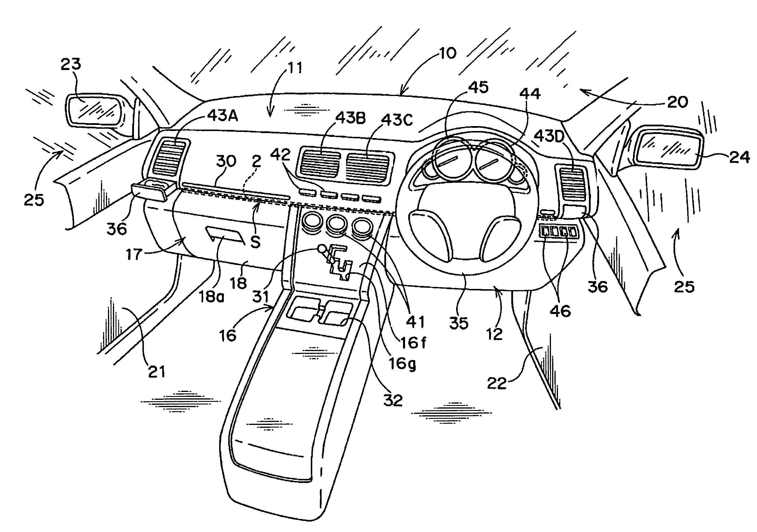
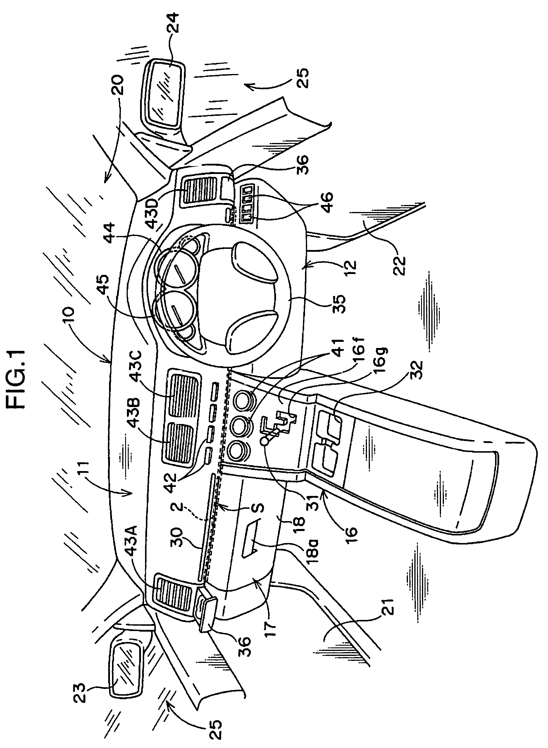
[0028]FIG. 1 is a schematic perspective view showing a front interior area of an automobile, which has a vehicle interior illumination structure according to the present invention. As shown in FIG. 1, an instrument panel 10 is installed in the front interior area of the automobile to cover a lower region of the front interior area, and a front windshield glass 20 is disposed to extend upward from the vicinity of the front edge of the instrument panel 10 so as to cover an upper region of the front interior area. That is, the front edge of the instrument panel 10 is located adjacent to the lower edge of the front windshield glass 20. A pair of side window glasses 25 are disposed, respectively, at laterally opposite outer ends of the front windshield glass 20 and on the rearward side of the front windshield glass 20. A front or upper portion of the instrument panel 10 has opposite lateral edges located adjacent to lower edges of the corresponding side window glasses 25.

[0029]The instru...

second embodiment

[0079]As shown in FIG. 8, in the second embodiment, an instrument panel 10 is formed with a pocket 51 located above a step portion S thereof and concavedly curved in the frontward direction of a vehicle. A lid portion 55 is provided to cover the pocket 51 in an openable and closable manner so as to form a glove box 50 above the step portion S.

[0080]The pocket 51 is composed of a separate member 56 (pocket member), for example, made of synthetic resin and formed in an approximately shape in section, and integrally joined to an step upper surface 11f of the instrument panel 10 at an upper edge and opposed right and left lateral edges thereof.

[0081]A groove portion 53 is formed below an opening of the pocket 51 to extend laterally, and an illumination member 2 is contained in the groove portion 53. The groove portion 53 has an approximately rectangular-shaped periphery in section, and the periphery has a top wall 53a and a bottom wall 53b which are made of transparent or semi-transluc...

third embodiment

[0090]The instrument panel 60 includes a center console unit 66 which extends from an approximately laterally central region thereof in a vertical and rearward direction of the vehicle. The center console unit 66 has a front upper region formed as an inclined portion provided with a gearshift lever 31. In the third embodiment, a plurality of manual setting dials 91 for an air-conditioning system are disposed on a rear side of the central region of the upper unit 61 of the instrument panel 60. Further, various types of manual operation buttons 92 and a display panel 99 for an audio system are disposed in a region of the instrument panel 60 on the front upper side of the manual setting dials 91.

[0091]Two conditioned-air outlet ports 93B, 93C are formed, respectively, on right and left sides of the display panel 99. Two conditioned-air outlet ports 93A, 93D are formed, respectively, in the vicinities of right and left ends of the upper unit 61 of the instrument panel 60. Various switch...


PUM


Abstract

Disclosed is a vehicle interior illumination structure comprising, in combination, an instrument panel 10 installed in a front interior area of a vehicle, and a light-guiding illumination member 2 disposed in the instrument panel. The instrument panel 10 is formed with a step portion S laterally extending at a height approximately equal to or above that of a mounting portion of a shaft of a steering wheel 35 to the instrument panel. The step portion S is defined in such a manner that a step upper surface 11f located on the upper side of the step portion and a step lower surface 12f located on the lower side of the step portion are formed in the instrument panel 10, and the step upper surface 11f has a rear edge 11p protruding in the rearward direction of the vehicle relative to a front edge 12p of the step lower surface 12f. The illumination member 2 is arranged to extend laterally at a position which is adjacent to the front edge 12p of the step lower surface 12f and capable of preventing illumination light of the illumination member 2 from directly coming within the field of view of a driver sitting in a front seat in the vehicle interior. The vehicle interior illumination structure of the present invention can prevent illumination light of the illumination member from obstructing the driver's view.

Description

TECHNICAL FIELD[0001]The present invention relates to a structure for illuminating the interior of a vehicle, such as an automobile, and more particularly to a vehicle interior illumination structure comprising, in combination, an instrument panel installed in a front interior area of a vehicle and a light-guiding illumination member disposed in the instrument panel.BACKGROUND ART[0002]Late years, with a view to providing sophisticated design of a vehicle interior and creating a tranquil atmosphere during illumination, various efforts have been made to adopt an indirect illumination technique to a system for illuminating the interior of a vehicle, such as an automobile, during the night etc., in place of a commonly used conventional technique, so-called “direct illumination”. Differently from the direct illumination technique designed to illuminate a target region by direct light from an illumination member capable of emitting illumination light, the indirect illumination technique ...

Claims


Application Information

Patent Timeline
Patent Type & Authority Patents(United States)
IPC IPC(8): B60Q1/00
CPCB60Q3/004B60Q3/0289B60Q3/042B60K2350/203B60Q3/64B60Q3/78B60Q3/12B60K2370/33
Inventor OKAZAKI, YASUAKIOCHIMIZU, HITOSHIHIRAMATSU, MASAYA
Owner MAZDA MOTOR CORP
Why Eureka
Try Eureka