Indicating plate for timepiece and production thereof

a technology of indicating plate and timepiece, which is applied in the direction of electric winding, instruments, horology, etc., can solve the problems of reducing the commercial value, limiting the inclusion of color tone, and affecting the production of timepieces

Inactive Publication Date: 2003-03-25
YAMAMOTO CORPORATION +1
View PDF12 Cites 32 Cited by
  • Summary
  • Abstract
  • Description
  • Claims
  • Application Information

AI Technical Summary

Benefits of technology

the timepiece indicating plate not only capable of preventing viewing of the solar cell from outside thereof through the timepiece indicating plate but also having a light transmission at least sufficient to cause the solar cell housed under the timepiece indicating plate to generate power.
It is preferred that the process comprise the step of covering the upper surface of the metallic thin film layer coating with a surface protective layer. For example, a color coating, a gradation coating or a laminate film can be used as the surface protective layer. The covering with the surface protective layer enables not only protecting the metallic thin film layer coating from oxidation, etc. but also effecting, for example, a tone change to thereby increase a design variation.

Problems solved by technology

Thus, not only is the design inclusive of color tone extremely restricted, but also the appearance is degraded to thereby lower the commercial value.
However, problems were encountered such that the supply of light energy to the solar cell was hampered and such that the appearance quality as watch dial was poor.
However, in this prior art, although the acrylic milk white plate is used as the scattering layer, a metal tone favored in an indicating plate of wristwatch and capable of imparting an appearance of superior quality can not be obtained.
Further, burrs occur at the time of working, thereby necessitating deburring.
Accordingly, the process is complicated and the cost is increased.
With respect to the half mirror coated with a matting clear lacquer, half mirror treatment and coating are required to thereby complicate the process.
Further, it is probable that, depending on coating operation, the film thickness becomes nonuniform to thereby cause a dispersion of transmission factor with the result that mottling occurs.
Moreover, with respect to the glass having one side thereof roughened by blasting or the white diffusion plate having a mirror formed of, for example, aluminum in a stripe or net pattern on a side opposite to plastic, blasting and mirror treatment are required to thereby complicate the process.
Furthermore, depending on these treatments, the problem is encountered such that the film thickness and irregularity degree become nonuniform to thereby invite a dispersion of transmission factor and a mottling.
Still further, all the above materials have a problem such that the appearance quality thereof as a watch dial is poor.
At any rate, the interposition of the above scattering layer between the color filter and the solar cell unfavorably requires a complicated process and invites a dispersion of transmission factor leading to a deterioration of power generation performance and an occurrence of mottling.
Further, a deterioration of appearance quality due to the property of material per se is invited.
However, the metallic indicating plate cannot be employed in the solar watch because the use of the metallic indicating plate intercepts light to thereby disenable the power generation by the solar cell.
Therefore, it has been unfeasible to realize an appearance of superior quality peculiar to metal color and an extensive design variation on the solar watch.
In particular, when the metallic thin film layer coating provided on the resin substrate is composed of Ag or Cu, the metallic thin film layer coating suffers from discoloration, rust, etc. unless a surface protective layer is present on the surface of the metallic thin film layer coating.

Method used


Image

  • Indicating plate for timepiece and production thereof
  • Indicating plate for timepiece and production thereof
  • Indicating plate for timepiece and production thereof

Examples


embodiment 1

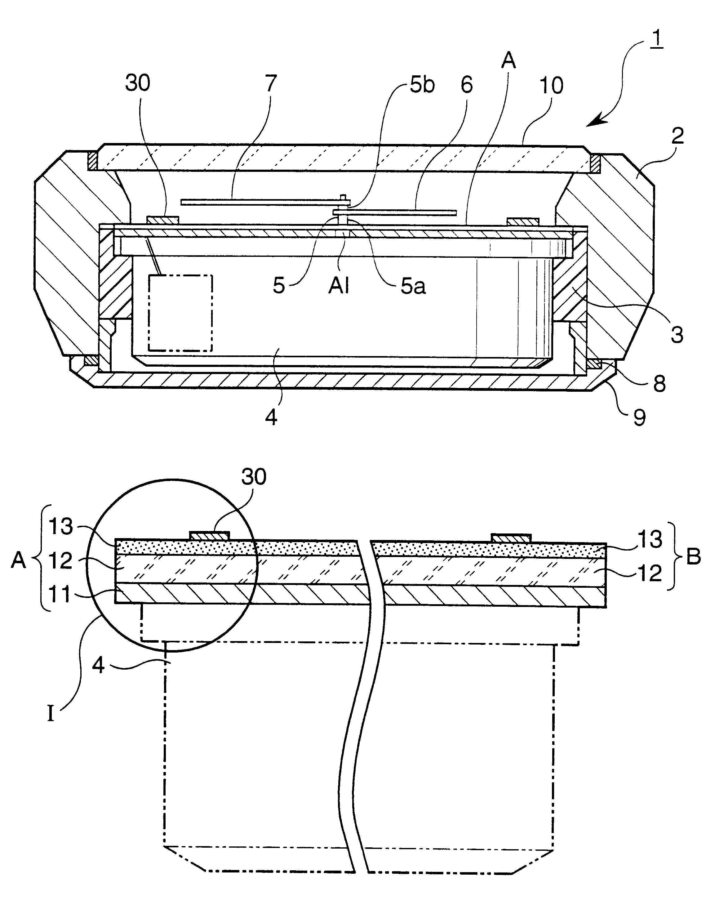
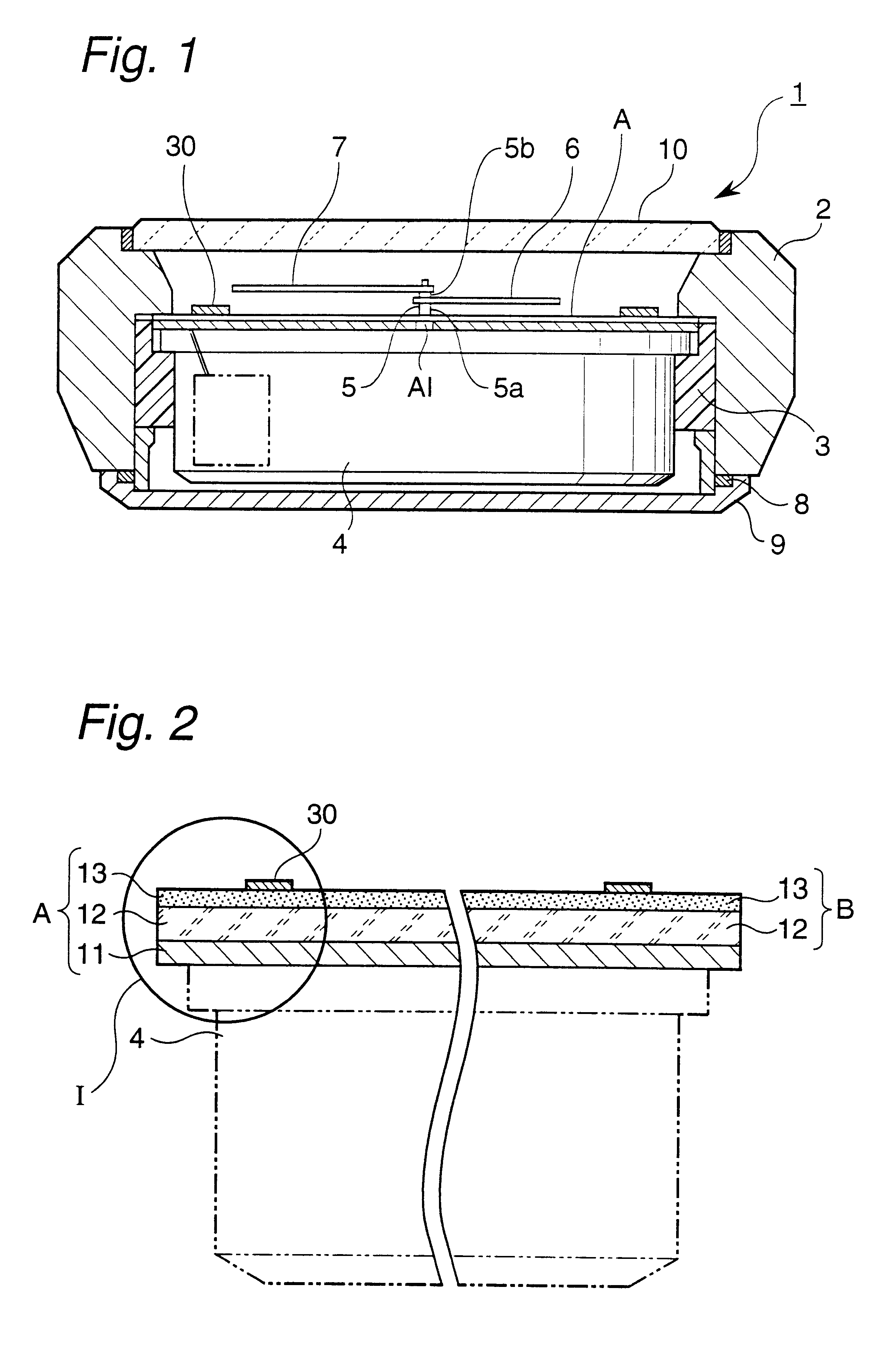
FIG. 1 is a sectional view of a wristwatch equipped with the timepiece indicating plate according to the first embodiment of the present invention; FIG. 2 is a sectional view of an indicating plate structure for solar timepiece equipped with the timepiece indicating plate according to the first embodiment of the present invention; and FIG. 3 is an enlarged view of portion I of FIG. 2.

Referring to FIG. 1, module 4 is fixed by means of support frame 3 of a synthetic resin, fitted in an internal part of outer barrel 2. Indicating plate structure for solar timepiece A is provided on a front side of the module 4. Hand axle 5 of a double axle construction provided on the module 4 is arranged through central hole Al made in the indicating plate structure for solar timepiece A. Outer axle 5a and inner axle 5b of the hand axle 5 are fitted with hour hand 6 and minute hand 7, respectively. Further, back lid 9 is secured through waterproof packing 8 to the bottom side of the outer barrel 2, an...

embodiment 2

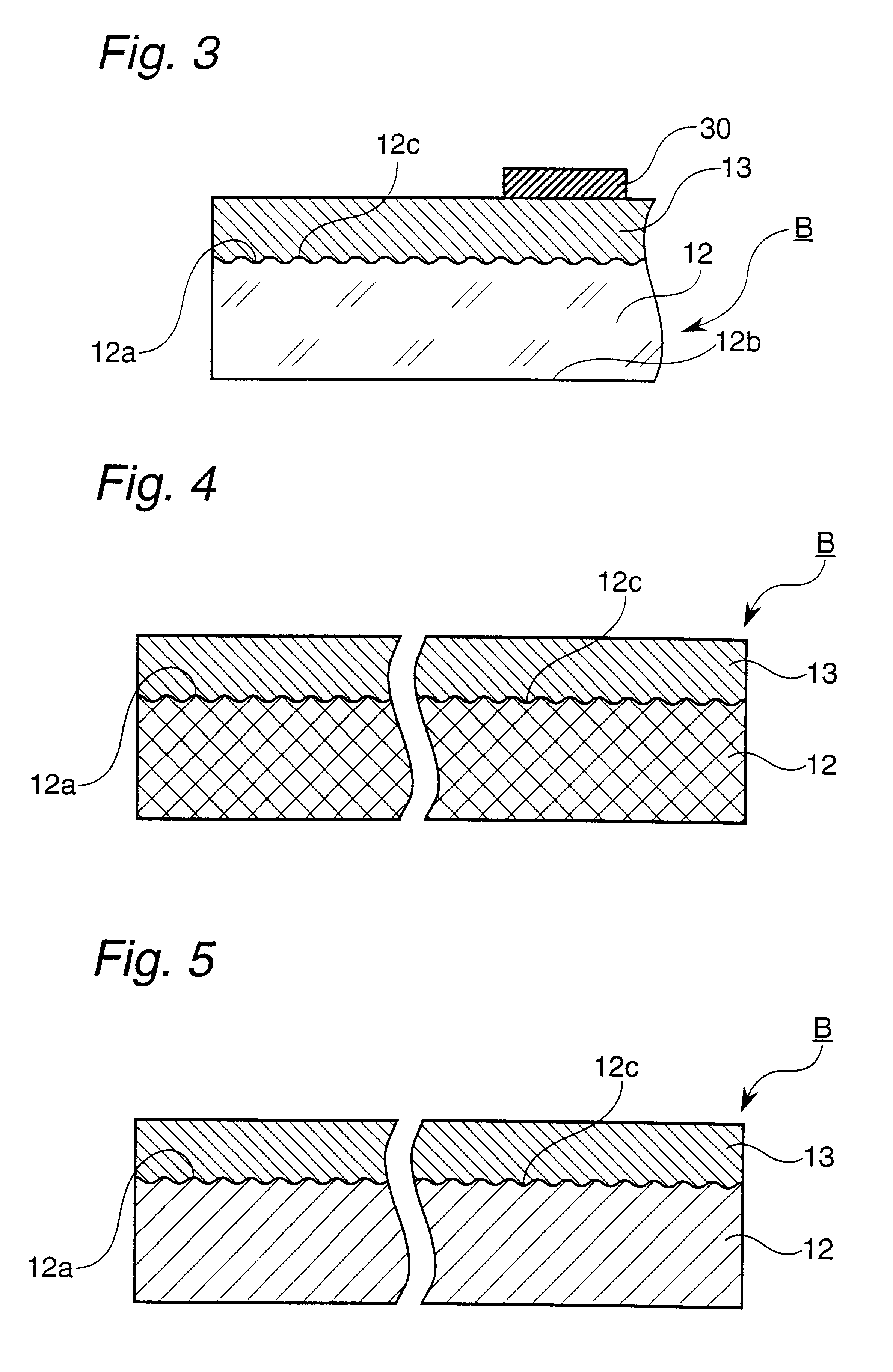
FIG. 4 is a sectional view of the timepiece indicating plate according to the second embodiment of the present invention.

The timepiece indicating plate B of this Embodiment is basically the same as that of Embodiment 1, for example, in that the metallic thin film layer 13 is formed on the surface of the front side (light incident side) 12a of the resin substrate 12 and in that the surface of the front side (light incident side) 12a of the resin substrate 12 is provided with minute irregularity pattern 12c. However, the timepiece indicating plate B of this Embodiment is different from that of Embodiment 1 in that a blend of different types of resins known as polymer alloy is used in the resin substrate 12. Thus, with respect to the same features as in Embodiment 1, the description thereof is omitted below.

In the resin substrate 12, a blend of different types of resins known as polymer alloy, for example, a polymer alloy consisting of a combination of at least two resins selected from...

embodiment 3

FIG. 5 is a sectional view of the timepiece indicating plate according to the third embodiment of the present invention.

The timepiece indicating plate B of this Embodiment is basically the same as that of Embodiment 1, for example, in that the metallic thin film layer 13 is formed on the surface of the front side (light incident side) 12a of the resin substrate 12 and in that the surface of the front side (light incident side) 12a of the resin substrate 12 is furnished with minute irregularity pattern 12c. However, the timepiece indicating plate B of this Embodiment is different from that of Embodiment 1 in that the resin substrate 12 is colored by the addition of a colorant such as a pigment or a dye. Thus, with respect to the same features as in Embodiments 1 and 2, the description thereof is omitted below.

For example, when the metallic thin film layer 13 is composed of silver, the whiteness of the silver tone can be increased by the addition of a white pigment such as titanium ox...


PUM


Abstract

An indicating plate for a timepiece is provided which is so structured as to prevent viewing of the solar cell and other items arranged thereunder through the indicating plate, which permits the same design expression as realized by the conventional metallic indicating plate and extensively increases a design variation inclusive of a ton (delicate hue) and pattern with superior-quality appearance and which has an excellent appearance quality to thereby ensure and enhance commercial value. The indicating plate for the timepiece is a timepiece indicating plate arranged on the front surface side of a solar cell housed in a timepiece. The timepiece indicating plate comprises a resin substrate through which light can be transmitted and metallic thin film layer coating formed on at least one side of the resin substrate by dry plating. The timepiece indicating plate not only is capable of preventing viewing of the solar cell from outside thereof through the timepiece indicating plate but also has a light transmission at least sufficient to cause the solar cell housed under the timepiece indicating plate to generate power.

Description

1. Technical FieldThe present invention relates to an indicating plate (dial) for a timepiece arranged on a front surface side of a solar battery (solar cell) housed in a timepiece, the solar cell capable of converting light energy to electric energy for utilization thereof.2. Background ArtIt is common practice to employ a solar cell as a power source for watches, desktop electronic calculators, portable radio sets, etc. This solar cell is generally constructed of, for example, amorphous silicon and converts light energy to electric energy. In view of this function, the solar cell must be arranged in a position upon which light is incident, i.e., a surface position such that the solar cell is directly visible from outside.The solar cell is commonly used in an indicating plate structure for wristwatch, which is constructed so that, referring to FIGS. 23 and 24, four solar cells 132 which are fan-shaped in a plan view are arranged, with an insulating band 133 therebetween, on an uppe...

Claims


Application Information

Patent Timeline
Patent Type & Authority Patents(United States)
IPC IPC(8): G04B19/12G04B19/06G04B19/14G04C10/00G04C10/02
CPCG04B19/12G04C10/02G04B19/14G04B19/06
Inventor YAMAGUCHI, KATSUYUKITAMARU, KATSUAKIIKEBUCHI, HIROSHI
Owner YAMAMOTO CORPORATION
Why Eureka
Try Eureka