
Power supply device and vehicle using same

a power supply device and power supply device technology, applied in the direction of batteries/cells, cell components, propulsion by batteries/cells, etc., can solve the problems of weight or cost increase, affecting the performance of the power supply device, etc., to achieve the effect of adequate strength

Active Publication Date: 2020-01-21
SANYO ELECTRIC CO LTD
View PDF11 Cites 0 Cited by
  • Summary
  • Abstract
  • Description
  • Claims
  • Application Information

AI Technical Summary

Benefits of technology

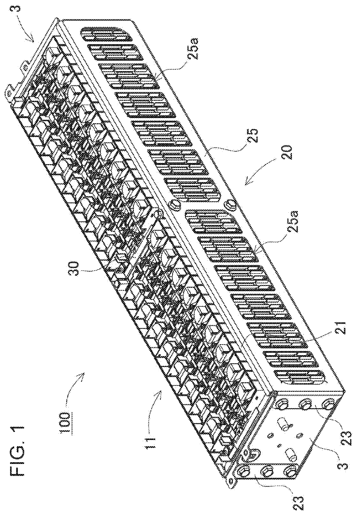
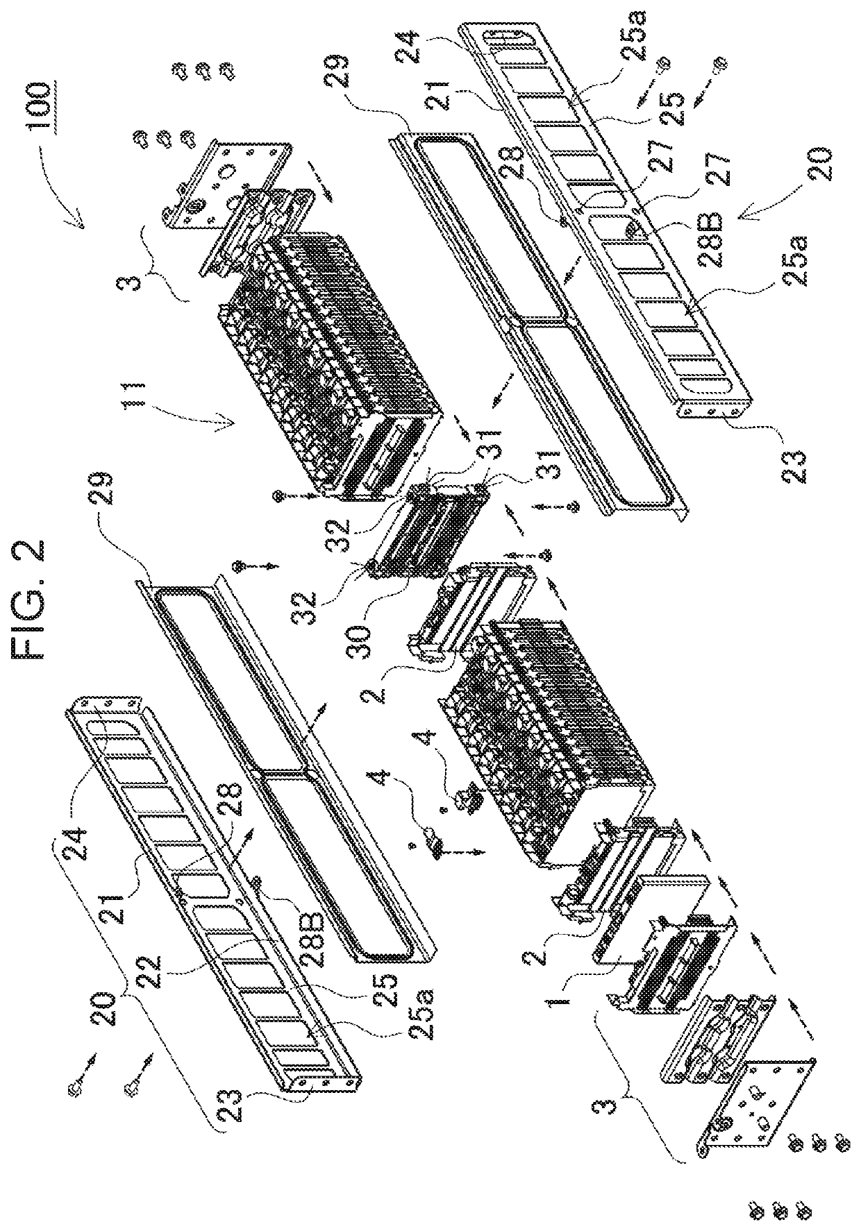
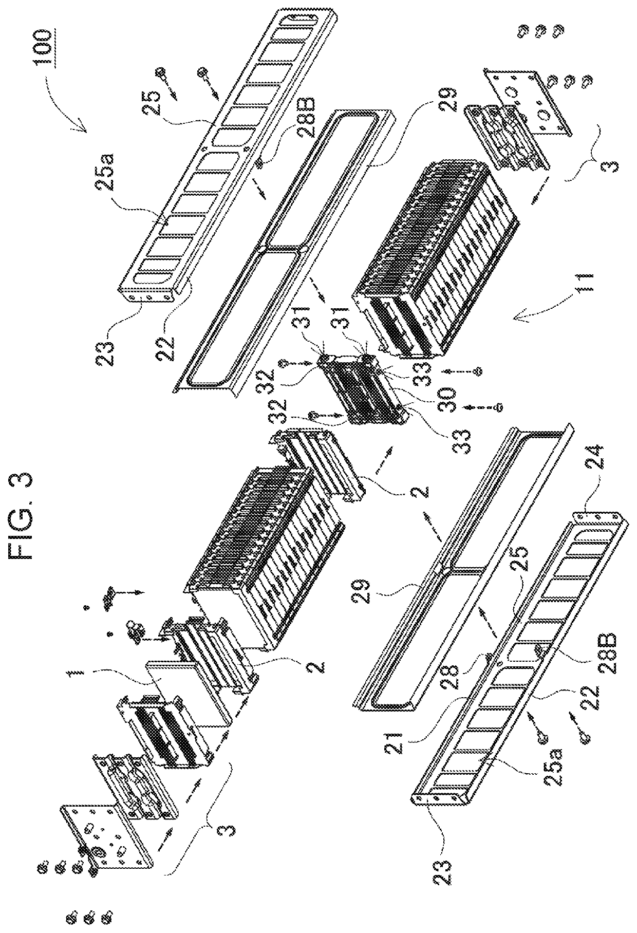
[0009]A first power supply device of the present invention includes: a plurality of secondary battery cells; separators having insulation property which are interposed between the adjacent secondary battery cells in a state where the plurality of secondary battery cells are stacked; end plates disposed at both end surfaces of a battery stacked body where the secondary battery cells and the separators are alternatively stacked; a pair of battery fastening members which fasten the end plates each other; and an intermediate bracket interposed at an intermediate portion of the battery stacked body. Further the pair of battery fastening members have fastening member-side fixing portions for fixing the intermediate bracket at an intermediate portion in a longitudinal direction of each of the pair of battery fastening members, and the intermediate bracket has bracket-side fixing portions which are fixed to the fastening member-side fixing portions. According to the above configuration, since intermediate part of the battery stacked body is reinforced by the intermediate bracket, there is a benefit of keeping rigidity even when the number of battery cells 1 to be stacked is increased.
[0018]According to a tenth power supply device, the intermediate bracket is disposed at a central location of the battery stacked body. According to the above configuration, the central portion is fixed in a well-balanced state, high hardness of the battery fastening member can be stably performed.

Problems solved by technology

As a result, problems in which the weight or cost is increased occur.
Also, as the number of the secondary battery cells increase, misalignment of the battery cells located at the center may occur largely.
However, in the above-mentioned configuration, since load caused by the section boards is applied to the rods for fastening in a shearing direction, the rods for fastening may be damaged.

Method used


Image

  • Power supply device and vehicle using same
  • Power supply device and vehicle using same
  • Power supply device and vehicle using same

Examples


modified example

[0072]As shown in the above-mentioned FIGS. 1 to 3, in battery fastening member 20, the end edges of fastening main surface 25 are bent. Otherwise, the bent end edge is further bent, and bent boards are fixed each other. This structure can improve strength. Such a example as battery fastening member 20B relating to the modified example, is shown in perspective views of FIG. 8A, FIG. 8B. An end edge of a longitudinal direction of second bent board 22 of each of battery fastening members 20B shown in these figures, projects from the end edge of fixing main surface 25, as projecting board 26. A projecting board-side screw hole 26h at projecting board 26 for screwing end plate 3, is open. In contrast, third screw hole 23h at third bent board 23 is open. Projecting board 26 is bent so as to overlap third bent board 23, as shown from a state of FIG. 8A to FIG. 8B. In this state, the projecting board-side screw hole is aligned to third screw hole 23h, and they are fixed to end plate 3 by a...


PUM

PropertyMeasurementUnit
lengthaaaaaaaaaa
hardnessaaaaaaaaaa
stressaaaaaaaaaa

Abstract

A power supply device includes: a plurality of secondary battery cells; separators having insulation property which are interposed between the adjacent secondary battery cells in a state where the plurality of secondary battery cells are stacked; end plates disposed at both end surfaces of a battery stacked body where the secondary battery cells and the separators are alternatively stacked; a pair of battery fastening members which fasten the end plates each other; and an intermediate bracket interposed at an intermediate portion of the battery stacked body. The pair of battery fastening members have fastening member-side fixing portions for fixing the intermediate bracket at an intermediate portion in a longitudinal direction of each of the pair of battery fastening members, the intermediate bracket has bracket-side fixing portions which are fixed to the fastening member-side fixing portions.

Description

[0001]This application is a U.S. national stage application of the PCT International Application No. PCT / JP2016 / 003269 filed on Jul. 11, 2016, which claims the benefit of foreign priority of Japanese patent application 2015-150281 filed on Jul. 30, 2015, the contents all of which are incorporated herein by reference.TECHNICAL FIELD[0002]The present invention relates to a power supply device and a vehicle using the same.BACKGROUND ART[0003]A power supply device using a secondary battery has been used for a power supply for driving a vehicle, for example. Such a power supply device generally has a configuration as shown in an exploded perspective view of FIG. 11. In FIG. 11, plural sheets of secondary battery cells 901 are stacked, and both ends thereof are covered with end plates 903, and then end plates 903 are fastened each other by right and left binding bars which are a pair of binding bars in each of right and left (for example, Patent Literature 1). When the output is increased...

Claims


Application Information

Patent Timeline
Patent Type & Authority Patents(United States)
IPC IPC(8): H01M6/42H01M2/16H01M2/10H01M50/209H01M50/264H01M50/293
CPCH01M2/1653H01M2/1077Y10S903/907H01M2220/20B60K1/04B60L50/64Y02T10/70Y02E60/10H01M50/293H01M50/209H01M50/264
Inventor BESSHO, TOSHIHIKOIMAI, KENICHI
Owner SANYO ELECTRIC CO LTD
Learn More