
Optical flatbed scanner with rigid transparent plate fixing

a flatbed scanner and transparent plate technology, applied in the field of scanner carriers, can solve the problems of unsolved problems relating to the deflection of the document platform, dust or wear traces eventually becoming visible on the underside of the transparent document platform, and the deflection of the transparent plate remains unresolved, so as to limit, rather than prevent, the deflection of the transparent plate. , the effect of relative accurate control of the deflection of the transparent pla

Active Publication Date: 2020-01-21
GLOBAL SCANNING DENMARK AS
View PDF4 Cites 0 Cited by
  • Summary
  • Abstract
  • Description
  • Claims
  • Application Information

AI Technical Summary

Benefits of technology

The patent text describes a device that uses a transparent plate to scan documents. The device has frame elements that help reduce bending of the plate, which improves the quality of the images produced by the scanner. The surface of the document is kept even when it is placed on the plate, even at a shallow focus depth. The glue seam used to connect the frame elements is cured using ultra-violet light, which prevents uneven tension and warp in the plate. Overall, the device ensures high-quality image reproduction.

Problems solved by technology

However this involves the problem that traces of dust or wear eventually becomes visible on the underside of the transparent document platform.
This will eventually cause image artefacts in the scanned document.
It should be noted that problems related to deflection of the document platform remains unsolved.
However, since the transparent member is lifted, at least where the line sensor is located to an elevated vertical position, high local strains will occur in the transparent member.
Further, the first supporting structure which is configured such that the transparent member is not deformed with respect to the reading line direction requires a very expensive precision frame of IT grade e.g. manufactured by precision grinding.
Still further, since the transparent member is allowed to move vertically between the first posture (flat) and the second posture (bent), the movable line sensor cannot be as accurately steered because reference markings or trails conventionally applied to the underside of the transparent member to accurately steer the movable line sensor will change their position when the transparent member moves
However, since first abutment members are provided on the contact type image sensor to maintain a fixed distance between the original table and the contact type image sensor, there will be generated traces, deposits, of dust on the original table.
This may be a problem even outside an effectively usable main scanning reading range of the contact type image sensor.
However, the above-mentioned problems persist also here.

Method used


Image

  • Optical flatbed scanner with rigid transparent plate fixing
  • Optical flatbed scanner with rigid transparent plate fixing
  • Optical flatbed scanner with rigid transparent plate fixing

Examples


Embodiment Construction

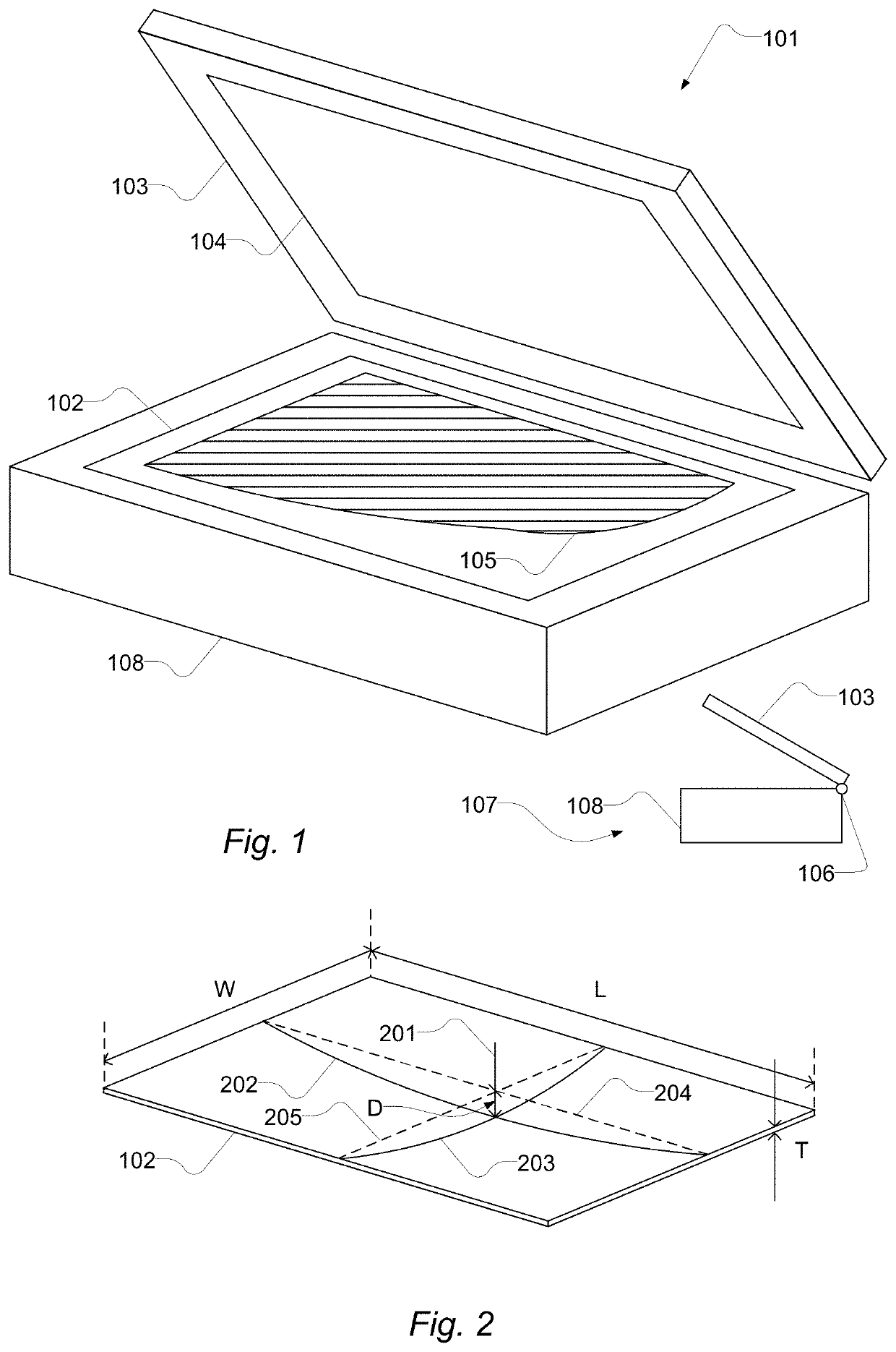
[0100]FIG. 1 shows a perspective view and a side-view of a flatbed scanner. The flatbed scanner 101 has a scanner body 108 which accommodates an electro-mechanical system comprising a camera and an optical system (not shown) performing scanning operations. The camera and the optical system may comprise one or more Contact Image Sensors. The flatbed scanner 101 has a transparent plate 102 whereon a document 105 can be placed with its side to be scanned facing the transparent plate for scanning as it is known in the art. Below the transparent plate 102, one or both of the camera and the optical system is arranged to move with a carriage to scan at least a portion of the document. The flatbed scanner 101 comprises a lid 103, which may be attached to the scanner body 108 by a hinge 106 as shown in the side-view 107. In some embodiments the lid 103 is movable relative to the scanner body 108 by one or more of an arm, a swivel and a hinge. The arm, swivel and / or hinge may have a gas sprin...


PUM


Abstract

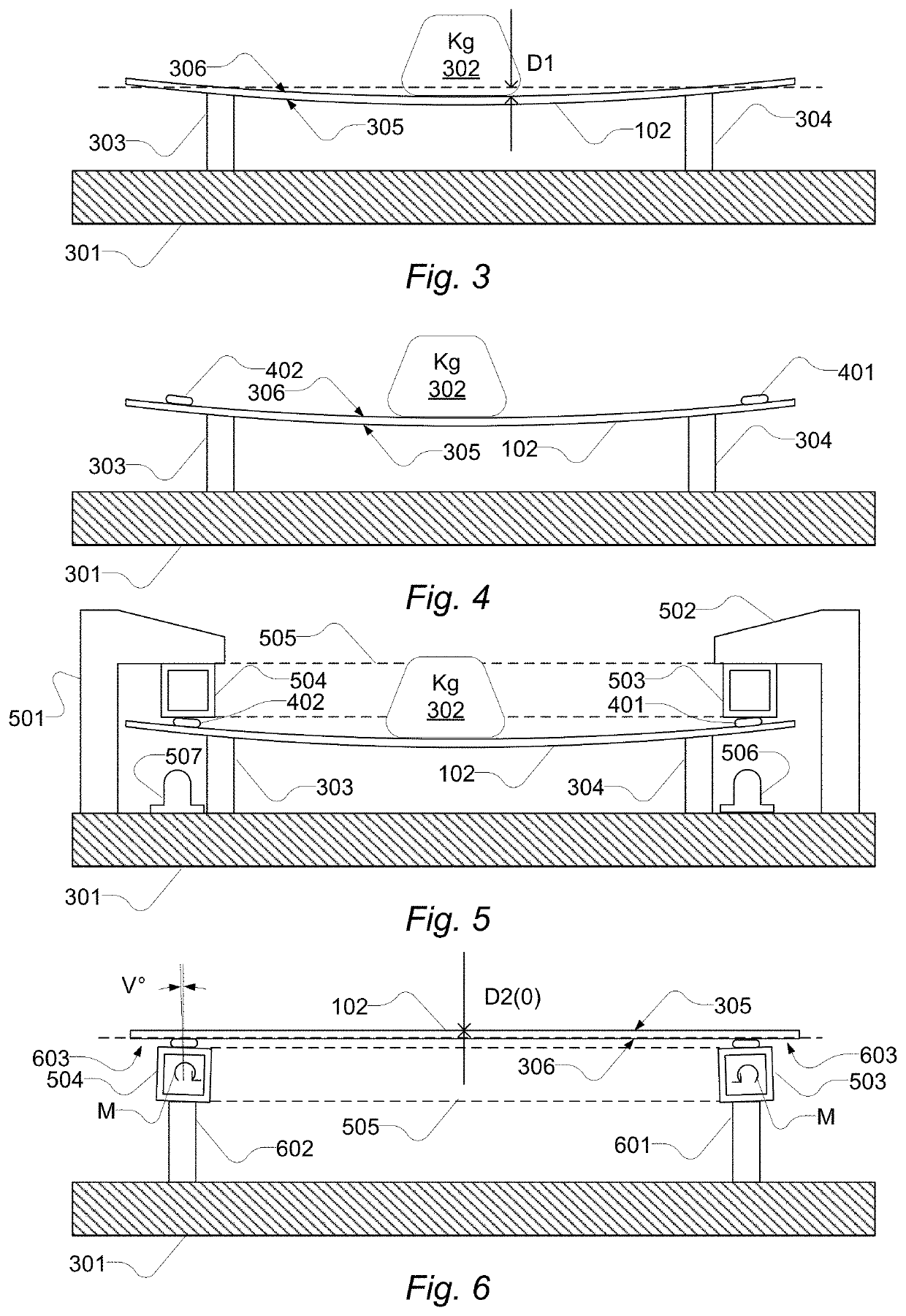
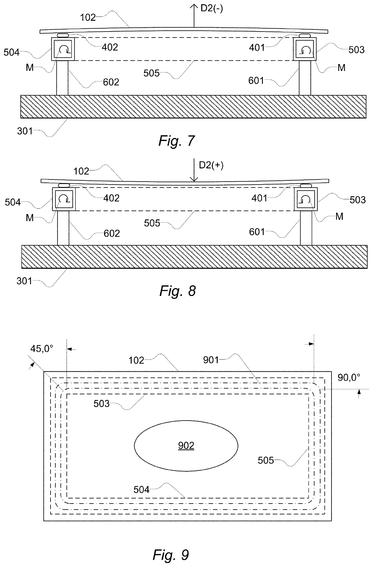
A flatbed scanner document scanner includes a large format document scanner body accommodating a rectangular rigid frame with an upwardly facing plane face and a rectangular transparent plate for supporting a large format document. The rectangular transparent plate overlies the upwardly facing plane face all around the metal frame. The scanner also includes a movable carriage configured to move along and below the rectangular transparent plate and carrying a line camera extending across the rectangular transparent plate. The rectangular transparent plate and the metal frame are bonded together by a hard glue seam that runs on the upwardly facing plane face of the metal frame. A predetermined deflected shape can be formed when the bonded plate and frame are turned upside-down. The rectangular metal frame can deform under its own load to a cambered shape, a flat shape or a less deflected shape when turned upright in a normal position.

Description

[0001]Conventional flatbed document scanners comprise a horizontally arranged transparent plate for supporting an original document which can be laid on and face towards the transparent plate. Below the transparent plate a longitudinal carriage extending across the full width of the transparent plate and carrying a movable line scanning camera or an optical system for a fixed line scanning camera moves in a direction at right angles to the orientation of the longitudinal carriage. While the longitudinal carriage, carrying the movable line scanning camera or the optical system, moves an electronic circuit acquires line image data from the line scanning camera to produce a digital image of the original. Thereby the document is scanned line-by-line. The document, which is a physical document, such as a sheet of paper, a book, a painting, may be denoted an original or an original document, whereas the digital image thereof may be denoted the reproduction or the reproduced document.[0002...

Claims


Application Information

Patent Timeline
Patent Type & Authority Patents(United States)
IPC IPC(8): H04N1/10H04N1/00
CPCH04N1/00557H04N1/1043H04N1/1065H04N1/00559H04N1/00249H04N1/00519H04N1/04H04N2201/02443H04N1/1013H04N1/192H04N2201/0422H04N2201/0446H04N2201/0456
Inventor KJÆR OLSEN, BO
Owner GLOBAL SCANNING DENMARK AS
Learn More