
Error smoothing through global source non-uniformity correction

Active Publication Date: 2020-01-21
DRS NETWORK & IMAGING SYST
View PDF21 Cites 10 Cited by
  • Summary
  • Abstract
  • Description
  • Claims
  • Application Information

AI Technical Summary

Benefits of technology

The present invention provides a method for improving the accuracy and consistency of infrared images by utilizing factory calibration data obtained through a shutter or thermal reference source. This data is combined with linear and quadratic non-uniformity correction techniques to provide enhanced performance. The invention can be used with a wide range of thermal imaging systems and offers improved response time compared to conventional methods.

Problems solved by technology

The difference in gain and offset values among detectors can produce fixed pattern noise in the image.

Method used


Image

  • Error smoothing through global source non-uniformity correction
  • Error smoothing through global source non-uniformity correction
  • Error smoothing through global source non-uniformity correction

Examples


Embodiment Construction

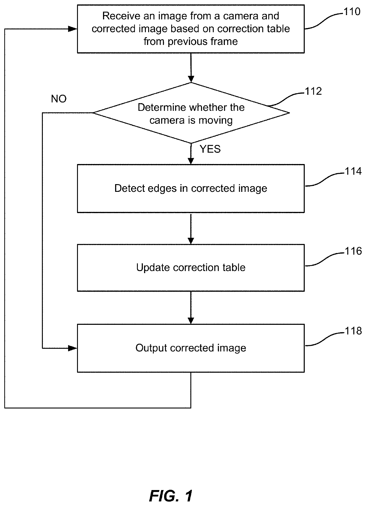
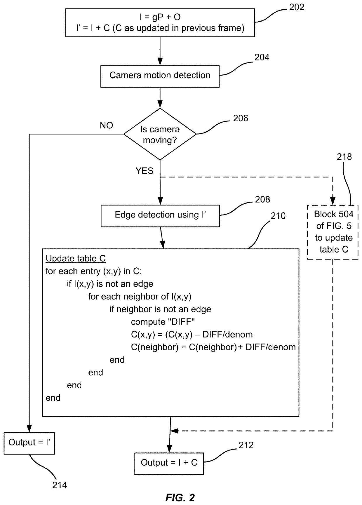
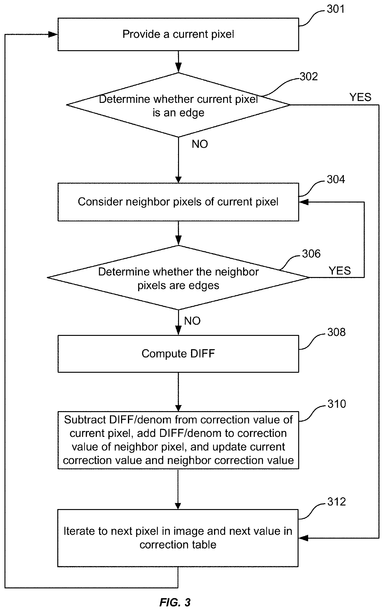
[0029]Embodiments of the present invention provide a method of correcting non-uniformity in infrared (IR) images. The method can incorporate a correction table that, when added to the image, corrects the drift associated with each pixel.

[0030]Infrared imagers may be devices used to capture and / or form infrared images, for example, a thermographic camera or infrared camera. Infrared imagers may include any device that forms an image using infrared radiation. Instead of the 450-750 nanometer range of the visible light camera, infrared cameras may operate in wavelengths as long as 14,000 nm (14 μm).

[0031]Infrared energy is a part of the electromagnetic spectrum, which encompasses radiation from gamma rays, x-rays, ultra violet, a thin region of visible light, infrared, terahertz waves, microwaves, and radio waves. The various categories of infrared radiation are related and differentiated in the length of their wave (wavelength). All objects emit a certain amount of infrared radiation ...


PUM


Abstract

A method of performing non-uniformity correction for an imaging system includes receiving image data from a detector. The method also includes retrieving stored correction coefficients from the memory. The method also includes retrieving a stored factory calibration reference frame. The method also includes acquiring an operational calibration reference frame. The method also includes computing updated correction coefficients based on the stored correction coefficients, the stored factory calibration reference frame, and the operational calibration reference frame. The method also includes computing the non-uniformity correction based on the updated correction coefficients. The method also includes forming a corrected image by applying the non-uniformity correction to the image data. The method further includes outputting the corrected image.

Description

BACKGROUND OF THE INVENTION[0001]The electromagnetic spectrum encompasses radiation from gamma rays, x-rays, ultra violet, a thin region of visible light, infrared, terahertz waves, microwaves, and radio waves, which are all related and differentiated in the length of their wave (wavelength). All objects, as a function of their temperatures, emit a certain amount of radiation. For example, the higher an object's temperature, the more infrared radiation the object emits.[0002]Thermal cameras have many applications, particularly when light and visibility are low. For example, thermal cameras have been used in military applications to locate human beings or other warm entities. Warm-blooded animals can also be monitored using thermographic imaging, especially nocturnal animals. Firefighters use thermal imaging to see through smoke, find people, and localize hotspots of fires. With thermal imaging, power line maintenance technicians locate overheating joints and parts, a telltale sign o...

Claims


Application Information

Patent Timeline
IPC IPC(8): H04N5/365H04N5/217H04N5/235H04N5/232H04N5/33G06T1/00G06T7/00G06T7/20G06T5/00H04N5/213H04N101/00
CPCH04N5/33G06T5/002G06T7/2006H04N5/213G06T1/0007H04N5/2355H04N5/217G06T7/0018H04N5/23229G06T2207/10048G06T2207/20182G06T2207/10004H04N2101/00G06T2207/20192H04N25/674H04N25/673H04N25/671H04N25/68H04N25/63G06T5/70G06T7/80G06T7/215H04N23/81H04N23/80H04N23/741
Inventor MARTENEY, STEVEN J.SOUTHERLAND, RICHARD L.JEPPSON, KRISTINA F.SKIDMORE, GEORGE
Owner DRS NETWORK & IMAGING SYST
Learn More