Device for controlling AC rotary machine and device for controlling electric power steering

a control device and rotary machine technology, applied in the direction of electronic commutators, dynamo-electric gear control, dynamo-electric converter control, etc., can solve the problems of large disadvantages in cost, space, reliability, etc., and achieve the effect of reducing torque ripple, reducing the s/n ratio, and reducing the vibration of both commands

Active Publication Date: 2020-01-28
MITSUBISHI ELECTRIC CORP
View PDF14 Cites 2 Cited by
  • Summary
  • Abstract
  • Description
  • Claims
  • Application Information

AI Technical Summary

Benefits of technology

[0015]According to the present invention, a phase difference is provided between the torque ripple, the sound, and the vibration generated by the first position estimation command and the torque ripple, the sound, and the vibration generated by the second position estimation command by providing the phase difference between the first position estimation command and the second position estimation command. As a result, the sum of the torque ripples, the sounds, and the vibrations of both of the commands is decreased compared with the case where both of the commands are in the same phase. Thus, the torque ripple, the sound, and the vibration generated by the AC rotary machine can be decreased with respect to the amplitude values of the first position estimation command and the second position estimation command compared with the related art.
[0016]In other words, according to the present invention, when the torque ripple, the vibration, and the sound need to be values equal to or less than respective predetermined values, the amplitudes of the first position estimation command and the second position estimation command can be set to larger values. As a result, the present invention can increase the S / N ratio, and decrease the influence of the quantization error caused by the AD resolution compared with the related art. Thus, the present invention suppresses the torque ripple, the vibration, and the noise of the high-frequency voltage signal components, and can increase the rotation position estimation accuracy, which are novel remarkable effects.

Problems solved by technology

However, when the rotation position sensor is separately provided, there is a great disadvantage in terms of cost, space, and reliability.

Method used


Image

  • Device for controlling AC rotary machine and device for controlling electric power steering
  • Device for controlling AC rotary machine and device for controlling electric power steering
  • Device for controlling AC rotary machine and device for controlling electric power steering

Examples


first embodiment

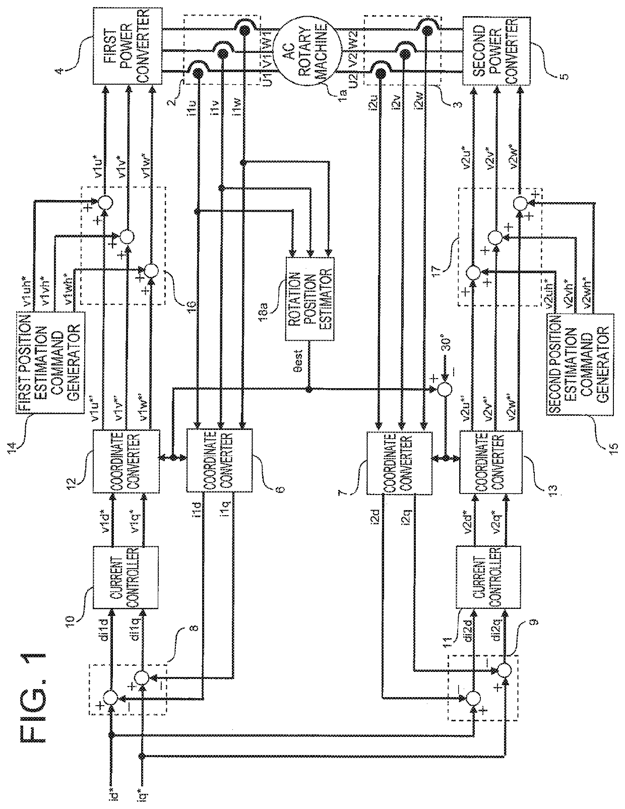
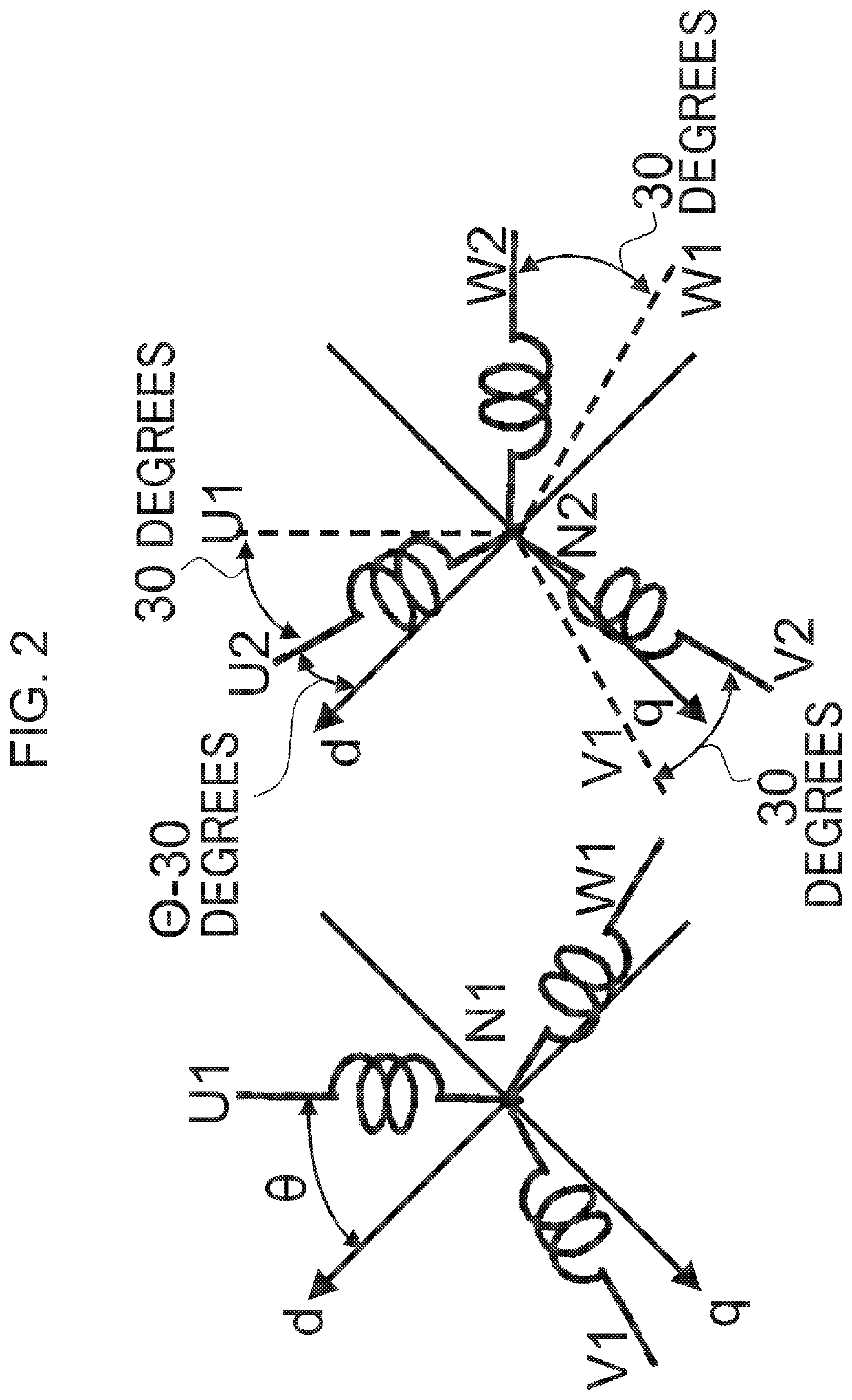
[0046]FIG. 1 is a diagram for illustrating an overall configuration of a control device for an AC rotary machine according to a first embodiment of the present invention. Further, FIG. 2 is a diagram for illustrating a configuration of a three-phase AC rotary machine used as the AC rotary machine in the first embodiment of the present invention. As illustrated in FIG. 2, an AC rotary machine 1a illustrated in FIG. 1 is a three-phase AC synchronous rotary machine in which first three-phase windings U1, V1, and W1 connected at a neutral point N1 and second three-phase windings U2, V2, and W2 connected at a neutral point N2 are stored in a stator of the rotary machine without an electrical connection.

[0047]The U1 winding and the U2 winding, the V1 winding and the V2 winding, and the W1 winding and the W2 winding respectively have a phase difference of 30 degrees from each other. In FIG. 2, a case in which both the first three-phase windings and the second three-phase windings have Y co...

second embodiment

[0103]FIG. 9 is a diagram for illustrating the overall configuration of the control device for an AC rotary machine according to a second embodiment of the present invention. Components corresponding to or similar to those of the first embodiment illustrated in FIG. 1 are denoted by the same reference symbols.

[0104]The configuration of FIG. 9 of the second embodiment is different from the configuration of FIG. 1 of the first embodiment in the following two points.[0105]A point that a subtractor 201 is further provided.[0106]A point that the rotation position estimator 18a is configured to calculate the estimated value θest of the rotation position based on the output of the subtractor 201.

[0107]The subtractor 201 is configured to calculate subtraction values iu_dif, iv_dif, and iw_dif by subtracting the second winding currents i2u, i2v, and i2w detected by the second current detector 3 from the first winding currents i1u, i1v, and i1w detected by the first current detector 2. Furthe...

third embodiment

[0115]FIG. 11 is a diagram for illustrating the overall configuration of the control device for an AC rotary machine according to a third embodiment of the present invention. Components corresponding to or similar to those of the first embodiment illustrated in FIG. 1 are denoted by the same reference symbols.

[0116]The configuration of FIG. 11 of the third embodiment is different from the configuration of FIG. 1 of the first embodiment in the following three points.[0117]A point that a first position estimation command generator 301, a second position estimation command generator 302, a superimposing device 303, and a superimposing device 304 are arranged at different positions in place of the first position estimation command generator 14, the second position estimation command generator 15, the superimposing device 16, and the superimposing device 17.[0118]A point that the first three-phase voltage commands v1u*′, v1v*, and v1w*′ output from the coordinate converter 12 are directl...


PUM


Abstract

When an AC rotary machine having a rotor structure for generating saliency, and including first three-phase windings and second three-phase windings is controlled, a first position estimation command to be superimposed on a voltage command or a current command directed to each of the first three-phase windings and a second position estimation command to be superimposed on a voltage command or a current command directed to each of the second three-phase windings are set to have the same frequency, and caused to have a phase difference, thereby increasing an estimation accuracy of a rotation position of the AC rotary machine.

Description

CROSS REFERENCE TO RELATED APPLICATIONS[0001]This application is a National Stage of International Application No. PCT / JP2015 / 065241, filed on May 27, 2015, the contents of all of which are incorporated herein by reference in their entirety.TECHNICAL FIELD[0002]The present invention relates to a control device for an AC rotary machine, and to an electric power steering device including the control device.BACKGROUND ART[0003]Rotation position information on an AC rotary machine and information on currents flowing through the AC rotary machine are necessary for accurately controlling a rotation operation of the AC rotary machine. The rotation position information is obtained by separately mounting a rotation position sensor to the AC rotary machine. However, when the rotation position sensor is separately provided, there is a great disadvantage in terms of cost, space, and reliability. Therefore, a sensorless configuration that uses a rotation position estimated value instead of the r...

Claims


Application Information

Patent Timeline
Patent Type & Authority Patents(United States)
IPC IPC(8): B62D5/04H02P9/06H02P6/18H02P21/24
CPCB62D5/0463H02P9/06H02P6/18H02P21/24H02P23/00H02P25/22H02P27/08H02P6/10H02P6/183H02P21/05
Inventor MORI, TATSUYANAKAJIMA, SHUNSUKEKEZOBO, ISAO
Owner MITSUBISHI ELECTRIC CORP
Why Eureka
Try Eureka