
Weather and wind buffeting resistant microphone assembly

a microphone and wind buffeting technology, applied in the field of weather and wind buffeting resistant external microphones, can solve the problems of additional challenges, weather, wind and other contaminants, and the use of external microphones on autonomous vehicles, and achieve the effect of preventing water, wind, wind buffeting, vibration or other noise factors

Active Publication Date: 2020-02-04
GM GLOBAL TECH OPERATIONS LLC
View PDF8 Cites 0 Cited by
  • Summary
  • Abstract
  • Description
  • Claims
  • Application Information

AI Technical Summary

Benefits of technology

[0006]In one aspect, the microphone assembly may further include a scrim layer connected to the cap and positioned between the microphone array and the gap. The scrim layer may be configured to minimize or prevent water or other contaminants from contacting the microphone array.
[0008]In one aspect, the microphone assembly may further include a membrane positioned between the microphone array and the scrim layer. The membrane may be configured to minimize or prevent water or other contaminants from contacting the microphone array.
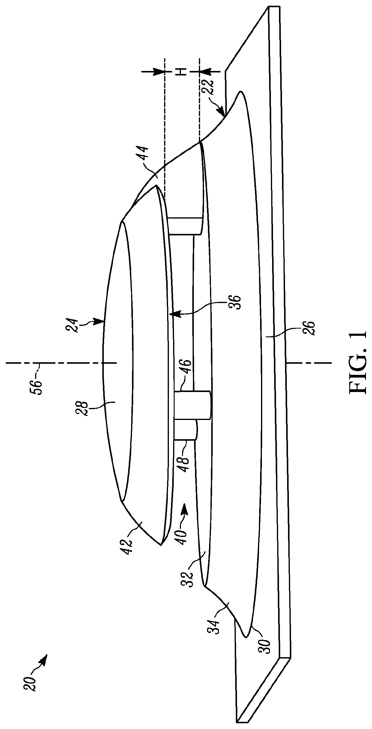
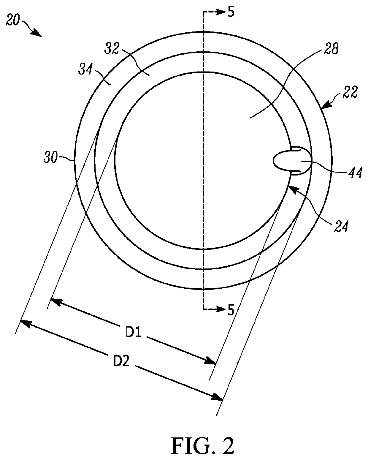
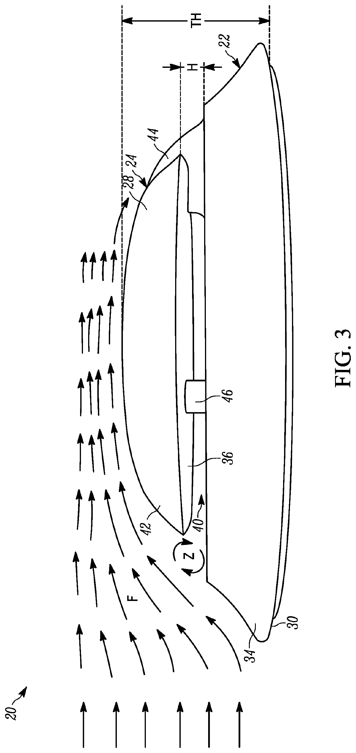
[0024]In another example, the present disclosure provides another microphone assembly for connection to an external panel of an autonomous vehicle. The microphone assembly includes a round base that includes a first surface, a second surface and a third surface. The first surface is configured to connect the base to the external panel of the autonomous vehicle. The second surface is positioned parallel to the first surface with the third surface positioned therebetween. The third surface defines an angled or curved shape to direct air flow that contacts the third surface in a direction away from the first surface. The microphone assembly also includes a round cap connected to the base by at least one support member. The cap includes a base-facing surface and a domed portion. The base-facing surface of the cap is vertically spaced apart from the second surface of the base to define a gap therebetween. The microphone assembly also includes a microphone array positioned inside a void in the cap. The microphone array includes a microphone substrate and at least three microphones. The at least three microphones are connected to the microphone substrate on a side of the microphone substrate opposite to the gap. The microphone substrate defines at least one aperture. The at least three microphones are configured to receive acoustic signals from the gap through the at least one aperture. The microphone assembly also includes a membrane that includes a porous or semi-porous material positioned over the at least one aperture of a gap-facing surface of the microphone substrate. The membrane is configured to minimize or prevent water or other contaminants from contacting the at least three microphones. The microphone assembly also includes a foam layer positioned adjacent the gap-facing surface of the microphone substrate. The foam layer is configured to reduce wind buffeting and noise directed toward the at least three microphones. The microphone assembly also includes a scrim layer positioned adjacent the foam layer on the base-facing surface of the cap to cover the void. The scrim layer is configured to minimize or prevent water or other contaminants from contacting the microphone array. The microphone assembly also includes a grill connected to the base-facing surface of the cap adjacent the scrim layer. The grill includes a border positioned adjacent the peripheral edge of the cap and a plurality of support bars extending inwardly from the border. The grill supports the scrim layer.

Problems solved by technology

Such external microphones are exposed to weather, wind and other contaminants.
The use of external microphones on autonomous vehicles presents additional challenges because air flows over and around the microphone when the vehicle is in motion.

Method used


Image

  • Weather and wind buffeting resistant microphone assembly
  • Weather and wind buffeting resistant microphone assembly
  • Weather and wind buffeting resistant microphone assembly

Examples


Embodiment Construction

[0042]Example embodiments are provided so that this disclosure will be thorough, and will fully convey the scope to those who are skilled in the art. Numerous specific details are set forth such as examples of specific compositions, components, devices, and methods, to provide a thorough understanding of embodiments of the present disclosure. It will be apparent to those skilled in the art that specific details need not be employed, that example embodiments may be embodied in many different forms and that neither should be construed to limit the scope of the disclosure. In some example embodiments, well-known processes, well-known device structures, and well-known technologies are not described in detail.

[0043]The terminology used herein is for the purpose of describing particular example embodiments only and is not intended to be limiting. As used herein, the singular forms “a,”“an,” and “the” may be intended to include the plural forms as well, unless the context clearly indicates...


PUM


Abstract

A microphone assembly includes a base that includes a first surface, a second surface and a third surface. The first surface is configured to connect the base to a mounting location in an external environment. The second surface is positioned parallel to the first surface with the third surface positioned therebetween. The third surface defines a curved shape to direct air flow that contacts the third surface in a direction away from the first surface. The microphone assembly also includes a cap disposed over and separated from the base by a gap. The cap includes a domed portion that has a convex shape that curves away from the second surface of the base. The microphone assembly also includes a microphone array that includes a plurality of microphones. The microphone array is disposed within the cap and is configured to receive acoustic signals from the external environment through the gap.

Description

INTRODUCTION[0001]This section provides background information related to the present disclosure which is not necessarily prior art.[0002]The present disclosure relates to a weather and wind buffeting resistant external microphone for the detection of acoustic signals.[0003]Microphones can be used to detect various acoustic signals in an external environment. Such external microphones are exposed to weather, wind and other contaminants. To ensure reliable and accurate detection of acoustic signals, external microphones are ideally protected from such exposure. One application for external microphones is for use on an autonomous vehicle to detect acoustic signals in the external environment. The use of external microphones on autonomous vehicles presents additional challenges because air flows over and around the microphone when the vehicle is in motion. It is desirable that such external microphones on autonomous vehicles need to reliably and accurately detect acoustic signals not o...

Claims


Application Information

Patent Timeline
Patent Type & Authority Patents(United States)
IPC IPC(8): H04R1/08H04R1/40H04R17/02
CPCH04R1/086H04R1/406H04R17/02H04R2499/13H04R2410/07H04R19/013G01H17/00H04R2201/003H04R29/005H04R2201/401
Inventor SHAHMURAD, BASSAM S.KARGUS, IV, WALTER A.SIFTON, STEPHEN M.
Owner GM GLOBAL TECH OPERATIONS LLC
Learn More