System and method for clot amelioration

a clot and system technology, applied in the field of medical devices and methods, can solve the problems of presenting a significant risk of injury to the blood vessel wall, failure to achieve sufficient thrombosis removal, and general ineffective emergency treatment, and achieve the effect of minimizing the risk of injury

Active Publication Date: 2019-07-16
WALZMAN INNOVATIONS LLC
View PDF4 Cites 0 Cited by
  • Summary
  • Abstract
  • Description
  • Claims
  • Application Information

AI Technical Summary

Benefits of technology

[0008]The present invention provides a device which may be deployed via a single lumen of a delivery catheter / sheath and capable of macerating with the distal end, irrigating from the distal end and aspirating from the distal end of said delivery catheter / sheath, and method for removing occlusive material from body lumens. The present invention is advantageous when compared to the prior art for effective removal of the occlusive material from the body lumen. In particular, the macerating element is the end of a lumen introduces coaxially into said first single lumen, which allows irrigation and maceration from the distal end of said lumen, thus it does not require a separate wire or cutting element and docs not require blades, and thereby eliminates the necessity of separate maceration device as well as the time necessary to deploy it, and the necessity of blades thus while minimizing the risk of injury to the blood vessel wall. Alternatively, it may eliminate the need for an addition catheter lumen for irrigation.
[0009]As described in detail below, the present invention employs both a lumen with a distal end capable of expansion and retraction, as well as rotating when desired, and irrigating for macerating or “dislocating” the thrombus, clot, or other occlusive material, when said lumen distal end is deployed proximally to a target site. The combined use of a single device to both mechanically macerate without blades and irrigate eliminates the necessity for precise positioning and minimizes or prevents contact between the present invention and the vessel / tissue wall, thus reducing or eliminating the potential for injury to the luminal wall. It should be noted that prior art such as U.S. Pat. No. 6,454,775 to Denise Demarais et al. (requires the maceration element to be carefully positioned (“the macerator is carefully positioned to minimize or prevent contact with and reduce or eliminate the potential for injury to the luminal wall”—see last sentence in SUMMARY OF THE INVENTION).
[0013]The present invention comprises system with a single lumen with a proximal end and a distal end. There are additional coaxial lumina within said single lumen. Said system comprises a catheter body having a proximal end located outside of a patient, and a distal end which is designed to move inside a patient. Said distal end may be angled and rotated using communication from said proximal end. In some embodiments it can be straight. In some embodiments it can have a complex shape. In some embodiments it can be sinusoidal. An expansible element may be deployed from a position near the distal end due to a communication from said proximal end. The present invention is capable of irrigating a target site and aspirating a target site using elements introduced through the same single lumen. The most outer concentric lumen is most often used for aspiration, while the most innermost concentric lumen is most often used for irrigation. Said distal end is capable of rotating in a helical or other shape to start to dislocate the occlusive material and said distal end may simultaneously irrigate the target site. Said distal end macerator is configured to disrupt occlusive material after a target site support element, such as a balloon is deployed to prevent the macerated material from moving away from the target site. Simultaneously, said distal end will aspirate said macerated material away from the target site and deliver it out of a hole near said proximal end. Additionally, in alternative from the rotational maceration, said distal end may contain a macerator that can be radially expansile, and can macerate via sequential radial expansion and contracting. With each cycle the wires of the macerator break up the clot. When desired, small changes in the location of the macerator can effectuate additional clot maceration as well. In such embodiments the macerator is a wire capture weaved coil or stent on the outside of the distal-most segment of the inner-most lumen, in which said wire capture device is attached at its end in a fixed fashion to said inner-most lumen / hypotube. The inner-most lumen is further contained within an intermediate lumen. The length of said intermediate lumen ends so that the unexpanded wire capture device spans the distance from its attachment to the inner-most lumen / hypotube to the distal end of said intermediate lumen, to which the proximal end of said capture device is permanently affixed as well. The inner-most lumen can be moved longitudinally relative to the intermediate lumen. When the innermost lumen is pulled back relative to the intermediate lumen, to shorten the distance between the ends of both lumens, the wire capture device is foreshortened, causing it to radially expand. Said wire capture device can thus be serially shortened / expanded and lengthened / unexpanded. Each time this is done said wires course through the debris / clot, thereby macerating said debris / clot into smaller pieces. In some embodiments there are additional side-holes along the length of said inner-most lumen that overlaps with the position of said capture device, allowing simultaneous irrigation into and distal to said debris.

Problems solved by technology

Said therapy is generally not effective in emergency situations due the amount of time (from several hours to several days) said therapy takes to work.
The prior art teach the use of thrombectomy procedures the use of rotating blades, however they present a significant risk of injury to the blood vessel wall.
Alternatively, those which rely primarily on vacuum extraction together with minimum disruption of the thrombus, often fail to achieve sufficient thrombus removal.

Method used


Image

  • System and method for clot amelioration
  • System and method for clot amelioration
  • System and method for clot amelioration

Examples


Embodiment Construction

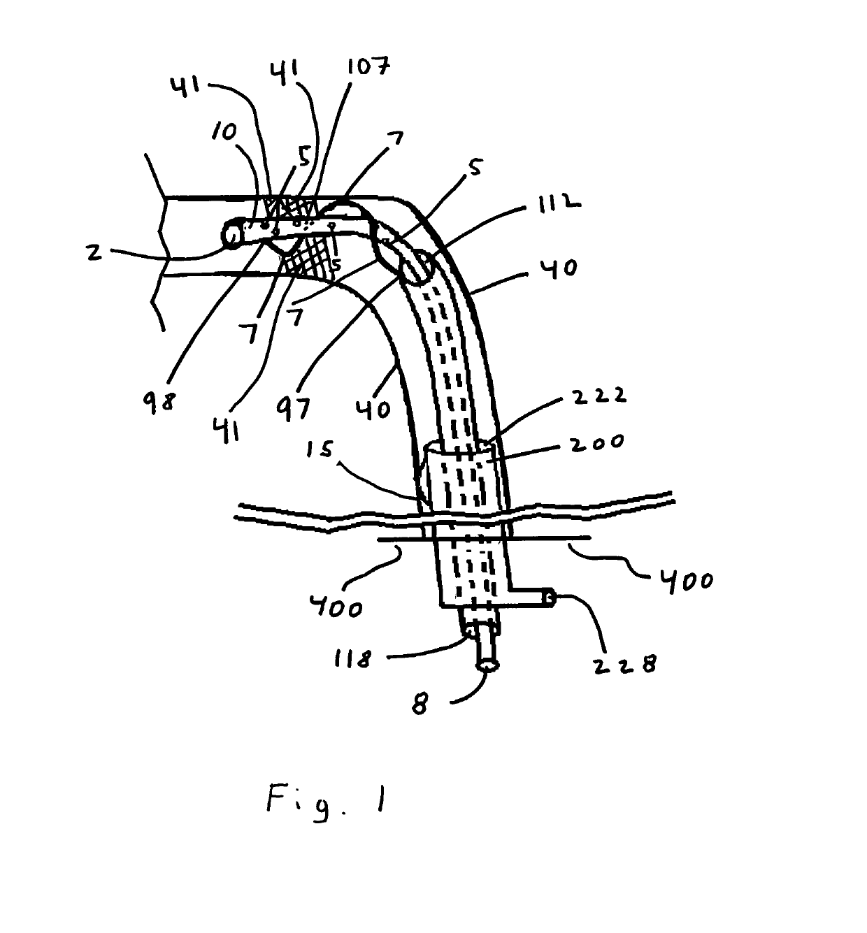
[0021]Referring now to FIG. 1, the present invention is disposed within vessel walls (40) and has impaled obstruction (41), typically a clot. The current invention is composed of three concentric sheaths, namely inner sheath (10), intermediate sheath (100), and outer sheath (200).

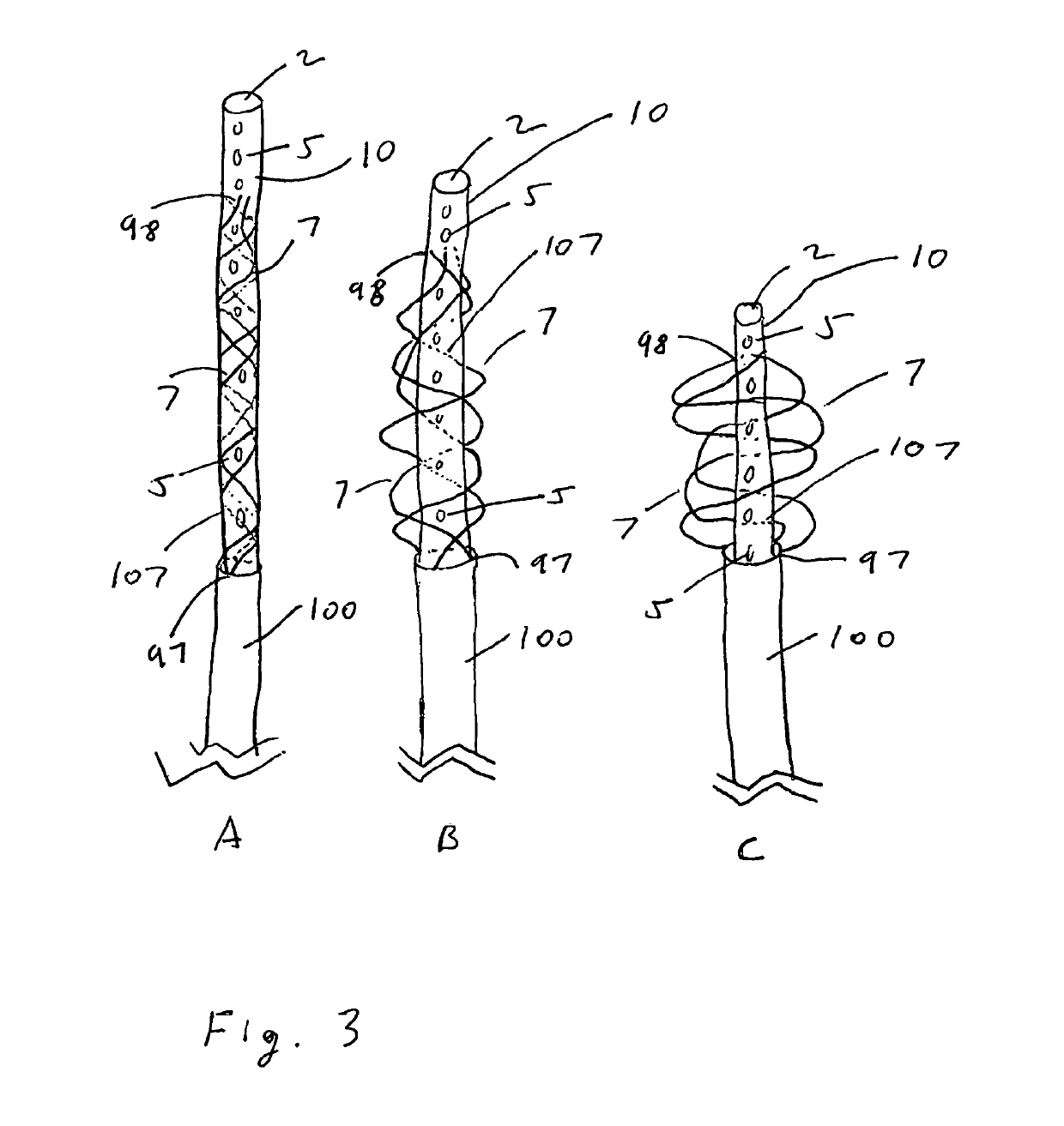
[0022]The first, innermost sheath is a hypotube (10) having a distal tip (2), a proximal tip (8), at least one perforation (5), and macerating elements (7). Proximal tip (8) communicates with an irrigation control system (not shown) to deliver irrigating fluid therethrough to perforations (5). Macerating elements (7) may be at least one wire or at least one stent attached to inner hypotube (10) at connection points (98). Macerating wire loops (7) are depicted in the embodiment illustrated. Obscured wires or loops (107) are depicted passing behind inner hypotube (10) as dotted lines to shown rotation. In some embodiments inner hypotube (10) may have an attached wire (not shown) extending from its distal end ...


PUM

PropertyMeasurementUnit
areaaaaaaaaaaa
blood pressureaaaaaaaaaa
timeaaaaaaaaaa

Abstract

A treatment of a medical difficulty associated with the formation or presence of a blood clot in a blood vessel, commonly known as “thrombectomy.” Said treatment may be achieved by introducing and positioning through a single lumen a device capable of macerating, irrigating and aspirating as well as supporting structures proximal to the distal end of said device. Said device is introduced via a blood vessel, and deployed at a treatment site. The macerator is then operated to dislocate thrombus, clot, or other occlusive materials at the target site, the irrigating element is then operated to continue to dislocate thrombus, clot, or other occlusive materials at the target site, and the aspirating element is used to collect and remove the disruptive materials from the target site.

Description

CROSS-REFERENCES[0001]Claims benefit of priority to provisional application 62 / 497,851 (filed Dec. 5, 2016) and continuation of non-provisional application Ser. No. 15 / 732,955 (filed Jan. 16, 2018)FEDERALLY FUNDED R&D[0002]NoneBACKGROUND OF THE INVENTIONField of the Invention[0003]The present invention relates generally to medical devices and methods. Specifically, the present invention teaches devices and methods for using a medical system for macerating, irrigating and aspirating, also capable of supporting structures proximal to the distal end of said device, for dislocating and removing occlusive material from blood vessels and other body lumens.Discussion of the Prior Art[0004]Thrombectomy is a medical treatment associated with the removal of occlusive material from blood vessels and other body lumens. Generally, removal of occlusive material from blood vessels and other body lumens is usually achieved by mechanically disrupting the clot. The disrupted thrombus or clot is then ...

Claims


Application Information

Patent Timeline
Patent Type & Authority Patents(United States)
IPC IPC(8): A61B17/3207A61B17/00A61M25/10
CPCA61B17/320758A61B2017/00477A61B2217/005A61B2217/007A61M25/10A61B2017/320716A61B17/221A61B17/320725A61B2017/22067A61B2017/22079A61B2017/22084A61F2220/0033A61F2250/0063A61L31/022A61L31/10A61L31/14A61L31/145A61L31/146A61L31/16A61L2430/06A61B17/12031A61B17/12113A61B17/12122A61B17/1214A61B17/12172A61B17/12177A61B17/1219A61B17/22032A61B2017/00867A61B2017/00893A61B2017/00898A61B2017/1205A61B2017/1209A61B2090/3966A61F2/852A61F2/91A61F2002/823A61F2002/826A61L29/145A61L29/16A61L31/04A61L31/125A61M2025/0057A61M2210/125
Inventor WALZMAN, DANIEL EZRA
Owner WALZMAN INNOVATIONS LLC
Why Eureka
Try Eureka